VectorStar™ MS464xB Series Microwave Vector Network Analyzer User Interface Reference : Calibration Menus – 2-Port VNAs : Manual Cal – Trans. Freq. Resp. Cal – 2-Port VNAs
 
Manual Cal – Trans. Freq. Resp. Cal – 2-Port VNAs
Note 
The appearance and button availability of the calibration menus depends on the settings established in the CAL SETUP, CAL METHOD, LINE TYPE menus and in the associated dialog boxes that appear from the Edit Cal Params button.
Full Name
Transmission Frequency Response Calibration
Menu Name
TRANS. RESPONSE
Button Name
Transmission Freq. Response


TRANS. RESPONSE Menu – 2-Port VNAs
Full Name
Transmission Frequency Response Calibration Setup
The exact composition of the menu depends on the settings made on the CAL SETUP, CAL METHOD, and LINE TYPE menus and on the resultant TRANSMISSION FREQUENCY REPONSE CAL SETUP dialog box. A representative menu is shown below. There is one example procedure of a Trans. Response calibration in this chapter.
Previous
MANUAL CAL Menu – 2-Port VNAs
Navigation
MAIN | Calibration | CALIBRATION | Calibrate | CALIBRATE | Manual Cal | MANUAL CAL | Transmission Freq. Response | TRANS. RESPONSE
TRANS. RESPONSE Menu – Trans. Freq. Resp. Cal. – 2-Port VNAs – Typical example (1 of 2)
Modify Cal Setup
Select displays the CAL SETUP menu where the Edit Cal Params button provides access to the TRANSMISSION FREQUENCY RESPONSE CAL SETUP dialog box for the selected calibration method and line type.
Example transmission frequency response calibration dialog boxes are available below:
A summary table of all transmission frequency response calibration configuration dialog boxes is available here:
Port Selected
Read-only display of the ports selected for the pending calibration.
 
Completion Menu Buttons
For this example menu, the Thru/Recip and Isolation (Optional) buttons link to completion submenus where additional calibration procedures are performed.
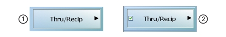
For example, the Thru/Recip button (shown below at #1) links to the THRU/RECIP submenu. As each procedure is completed, the submenu button is marked with a completion checkmark. When all the procedures on the submenu are completed, use the Back button to return to the TRANS. RESPONSE menu.
The Thru/Recip button (shown above at #2) is now marked with a completion checkmark.
Thru/Recip
When selected, displays the THRU/RECIP menu. When all tasks are complete, return to the TRANS. RESPONSE menu.
Isolation (Optional)
When selected, displays the ISOLATION menu. When all tasks are completed, return to the TRANS. RESPONSE menu.
Done
This button is unavailable until all calibration tasks have been successfully completed. When available, select the button to return to the CALIBRATION menu when the Cal Status is set to ON.
Abort Cal
Select aborts the current calibration and returns to the CALIBRATION menu.
TRANS. FREQ. RESP. CAL. SETUP (SOLT/R – Coaxial) Dialog Box
Full Name
Transmission Frequency Response Calibration Setup
Previous
TRANS. RESPONSE Menu – 2-Port VNAs
CAL SETUP Menu
Prerequisites
Cal Method = SOLT/SOLR
Line Type = Coaxial
Navigation
MAIN | Calibration | CALIBRATION | Calibrate | CALIBRATE | Manual Cal | MANUAL CAL | Transmission Freq Response | TRANS FREQ (TRANSMISSION FREQUENCY RESPONSE) | Modify Cal Setup | CAL SETUP | Edit Cal Params | TRANSMISSION FREQUENCY RESPONSE CAL SETUP (SOLT/R, Coaxial) Dialog Box
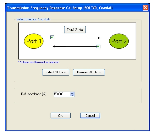
TRANS. FREQ. RESP. CAL. SETUP (SOLT/R, Coaxial) Dialog Box
TRANSMISSION FREQUENCY RESPONSE CALIBRATION SETUP Dialog Box
Select Direction And Ports
Select any combination of the two available Throughs. At least one thru must be selected. Both the Thru Port 1 to Port 2 and the Thru Port 2 to Port 1 may be selected.
Thru 1-2 Info Button
Select the Thru 1-2 to display the THRU INFO dialog box.
The THRU INFO dialog box is described above in THRU INFO Dialog Box – 2-Port VNAs
The Calculator icon is available on the THRU INFO dialog box. Select displays the AIR EQUIVALENT LENGTH CONVERSION dialog box.
The AIR EQUIVALENT LENGTH CONVERSION dialog box is described above in AIR EQUIVALENT LENGTH CONVERSION Dialog Box – 2-Port VNAs.
Reference Impedance
Input the reference impedance.
Input field defaulted to 50 Ohms.
Any numerical value accepted, although input values < 0.01 Ohms are converted to 0.01 Ohms.
Transmission Frequency Response Calibration Setup Dialog Boxes
The table below summarizes the available fields and controls in other transmission frequency response calibration setup dialog boxes (abbreviated in this section as Trans. Freq. Resp. Cal.). To view each dialog box, set the CAL METHOD and LINE TYPE menus to the appropriate settings, and then select the Edit Cal Params button.
Manual Calibration – Trans. Freq. Resp. Cal. Setup Dialog Box Contents – 2-Port VNAs (1 of 2)
Cal Method
Line Type
Dialog Box Input Selections and Controls
SOLT/R
Coaxial
 
Select Direction and Ports: Port 1, Port 2, Port 1 and Port 2
Reference Impedance (Ohms)
SOLT/R
Non-Dispersive
Same controls and functions as SOLT/R Coaxial.
SOLT/R
Waveguide
Same controls and functions as SOLT/R Coaxial with the following changes:
 
Waveguide Kit: User-Defined 1 to User-Defined 32
Waveguide Info button: Displays USER DEFINED WAVEGUIDE dialog box.
SOLT/R
Microstrip
Same controls and functions as SOLT/R Coaxial with the following changes:
 
Microstrip Kit: 10 Mil Kit, 15 Mil Kit, 25 Mil Kit, User-Defined 1 to User-Defined 32
Microstrip Info button: Displays info dialog box for selected calibration method and kit.
SSLT
Coaxial
Same controls and functions as SOLT/R Coaxial above.
SSLT
Non-Dispersive
Same controls and functions as SOLT/R Coaxial above.
SSLT
Waveguide
Same controls and functions as SOLT/R Coaxial with the following changes:
 
Waveguide Kit: User-Defined 1 to User-Defined 32
Waveguide Info button: Displays USER DEFINED WAVEGUIDE dialog box.
SSLT
Microstrip
Same controls and functions as SOLT/R Coaxial with the following changes:
 
Microstrip Kit: 10 Mil Kit, 15 Mil Kit, 25 Mil Kit, User-Defined 1 to User-Defined 32
Microstrip Info button: Displays info dialog box for selected calibration method and kit.
SSST
Coaxial
Same controls and functions as SOLT/R Coaxial above.
SSST
Non-Dispersive
Same controls and functions as SOLT/R Coaxial above.
SSST
Waveguide
Same controls and functions as SOLT/R Coaxial with the following changes:
 
Waveguide Kit: User-Defined 1 to User-Defined 32
Waveguide Info button: Displays USER DEFINED WAVEGUIDE dialog box.
SSST
Microstrip
Same controls and functions as SOLT/R Coaxial with the following changes:
 
Microstrip Kit: 10 Mil Kit, 15 Mil Kit, 25 Mil Kit, User-Defined 1 to User-Defined 32
Microstrip Info button: Displays info dialog box for selected calibration method and kit.
TRL/TRM
The TRL/TRM calibration method is not available for Transmission Frequency Response calibrations.
LRL/LRM
The LRL/LRM calibration method is not available for Transmission Frequency Response calibrations.
mTRL
The mTRL calibration method is not available for Transmission Frequency Response calibrations.
mSSS
The mSSS calibration method is not available for Transmission Frequency Response calibrations.