Manual Calibration General Dialog Boxes – 2-Port VNAs
The dialog boxes displayed below are representative of standard and user-defined dialog boxes associated with the calibration function. Most of these dialog boxes can be called from multiple locations.
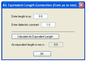
AIR EQUIVALENT LENGTH CONVERSION Dialog Box – 2-Port VNAs
Use the AIR EQUIVALENT LENGTH CONVERSION dialog box to speed configuration of a thru line by entering its length in picoseconds (ps) and its dielectric constant. The calculator returns the air equivalent length in millimeters (mm).
Previous
• The AIR EQUIVALENT LENGTH dialog box can be accessed from multiple locations.
• MAIN | Calibration | CALIBRATION | Calibrate | CALIBRATE | Manual Cal | MANUAL CAL | 2-Port Cal | TWO PORT CAL | Modify Cal Setup | CAL SETUP | Edit Cal Params | TWO PORT CAL SETUP dialog | Through/Reciprocal Length Calculator Icon | AIR EQUIVALENT LENGTH Dialog Box‘
AIR EQUIVALENT LENGTH CONVERSION Dialog Box
Using the Calculator
1. Use the Enter length in ps (picoseconds) to input a length.
• For example, enter a value of 250 ps.
2. Use the Enter constant to change the dielectric constant as required.
• For example, change the dielectric constant to 1.2.
3. Click the Calculate Air Equivalent Length button.
4. The required value appears in the Air Equivalent Length in mm field.
• Using the examples above, an air equivalent length of 68.465319... appears in the field.
5. Click OK.
6. The THRU INFO dialog box reappears with the calculated value in the Length (mm) field.
7. Using the examples above, the Length (mm) field displays 68.4653 mm.
• Microstrip Kit = 10 Mil Kit, 15 Mil Kit, or 25 Mil Kit
Navigation
• MAIN | Calibration | CALIBRATION | Calibrate | CALIBRATE | Manual Cal | MANUAL CAL | 2-Port Cal | TWO PORT CAL | Modify Cal Setup | CAL SETUP | Edit Cal Params | TWO PORT CAL SETUP (SOLT/R, Microstrip) | Microstrip Kit = 10 Mil Kit, 15, Mil Kit, or 25 Mil Kit | Microstrip Info button | MICROSTRIP INFO (Selected Kit) Dialog Box
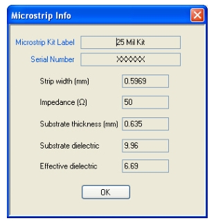
MICROSTRIP INFO (10 MIL KIT) Dialog Box
The read-only dialog box provides the calibration parameters for the selected microstrip kit. The displays for 10 Mil, 15 Mil, and 25 Mil Kits are identical.
The calibration parameters listed are:
• Microstrip Kit Label
• Microstrip Kit Serial Number
• Strip width (mm)
• Impedance (Ohms)
• Substrate thickness (mm)
• Substrate dielectric value
• Effective dielectric value
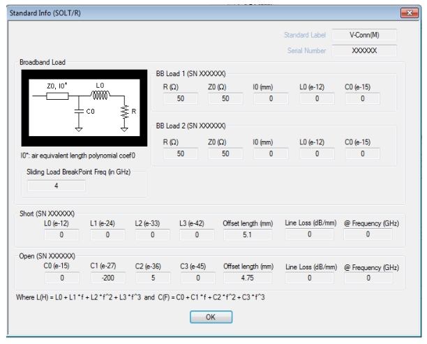
STANDARD INFO Dialog Box – 2-Port VNAs
The exact title and contents of the dialog box depend on the calibration method and connector types selected. This dialog box displays parametric information for a standard connector such as a V-connectors. For the equivalent dialog box for a user-defined connector, see USER DEFINED STANDARD Dialog Box – 2-Port VNAs.
Previous
• The STANDARD INFO dialog box can be accessed from multiple locations.
• MAIN | Calibration | CALIBRATION | Calibrate | CALIBRATE | Manual Cal | MANUAL CAL | 2-Port Cal | TWO PORT CAL | Modify Cal Setup | CAL SETUP | Cal Method = SOLT/SOLR | Line Type = Coaxial | Edit Cal Params | TWO PORT CAL SETUP (SOLT/R, Coaxial) | DUT Connector = V-Conn(M) | Standard Info button | STANDARD INFO (SOLT/R, V-CONN M) Dialog Box
STANDARD INFO (SOLT/R, V-CONN M) Dialog Box
The read-only dialog box provides the calibration parameters for the selected connector and calibration method.
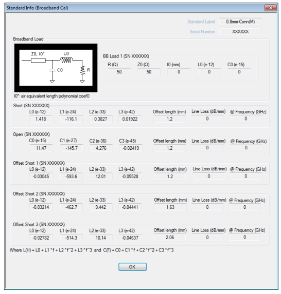
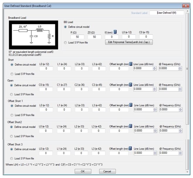
STANDARD INFO (Broadband Cal) 0.8 mm (M) Connector Dialog Box
• MAIN | Calibration | CALIBRATION | Calibrate | CALIBRATE | Manual Cal | MANUAL CAL | 2-Port Cal | TWO PORT CAL | Modify Cal Setup | CAL SETUP | Cal Method = Broadband Cal (SOLT/R-SSST/R) | Line Type = Coaxial | Edit Cal Params | TWO PORT CAL SETUP BROADBAND CAL, MERGED SOLT-SSST/SOLR-SSSR) Dialog Box | DUT Connector = 0.8 mm-Conn (M) | Standard Info | STANDARD INFO (Broadband)
Standard Info (Broadband Cal) Dialog
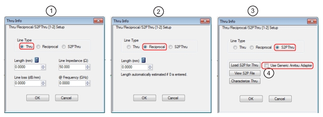
THRU INFO Dialog Box – 2-Port VNAs
Use the THRU INFO dialog to update the thru information for most calibration types. The dialog includes access to the AIR EQUIVALENT LENGTHCONVERSION dialog box to speed configuration.
• Allows a thru characterization and generation of an .s2p file.
• Use Generic Anritsu Adapter (check box)
• Checking this box will automatically load a default .s2p file for a generic Anritsu adapter. Note that selecting the checkbox disables the Load S2P for Thru and Characterize Thru buttons.
• MAIN | Calibration | CALIBRATION | Calibrate | CALIBRATE | Manual Cal | MANUAL CAL | 2-Port Cal | TWO PORT CAL | Modify Cal Setup | CAL SETUP | Cal Method = TRL/TRM | Edit Cal Params | TWO PORT CAL SETUP (TRL/TRM, Coaxial) | Band X = Match | Match Info button | USER DEFINED MATCH DEVICES Dialog Box
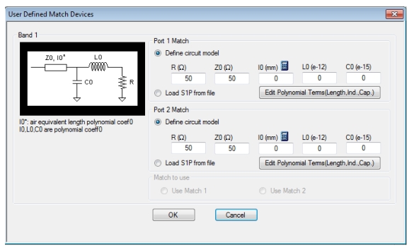
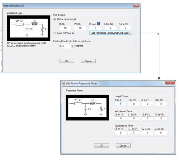
Example: USER DEFINED MATCH DEVICES Dialog Box – TRL/TRM
Description
This dialog box allows the definition of a user-provided match device.
Port 1 Match
Define the Port 1 Match device by entering the following parameters:
• R (Ohms)
• Z0 (Ohms)
• l0 (mm)
• If required, a link is available to the AIR EQUIVALENT LENGTH CONVERSION dialog box:
• MAIN | Calibration | CALIBRATION | Calibrate | CALIBRATE | Manual Cal | MANUAL CAL | 2-Port Cal | TWO PORT CAL | Modify Cal Setup | CAL SETUP | Cal Method = LRL/LRM | Edit Cal Params | TWO PORT CAL SETUP (LRL/LRM, Coaxial) | Band 1 Device 2 = Match | Match Info button | USER DEFINED MATCH DEVICES Dialog Box
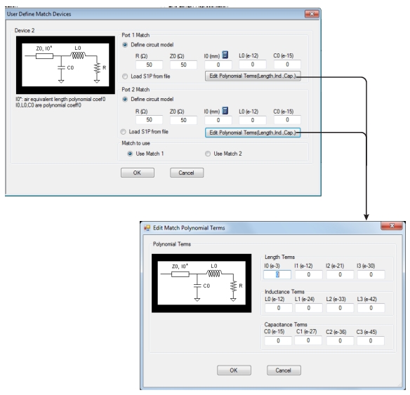
USER DEFINED MATCH DEVICES Dialog Box – LRL/LRM 2-Port VNAs
Description
This dialog box allows the definition of a user-provided match device.
Port 1 Match
Define the Port 1 Match device by entering the following parameters:
• R (Ohms)
• Z0 (Ohms)
• l0 (mm)
• If required, a link is available to the AIR EQUIVALENT LENGTH CONVERSION dialog box:
• MAIN | Calibration | CALIBRATION | Calibrate | CALIBRATE | Manual Cal | MANUAL CAL | 2-Port Cal | TWO PORT CAL | Modify Cal Setup | CAL SETUP | Cal Method = mTRL | Edit Cal Params | TWO PORT CAL SETUP (mTRL, Coaxial) | Use Match | Match Info button | USER DEFINED MATCH DEVICES Dialog Box
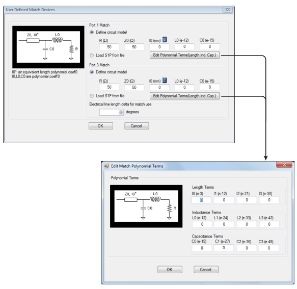
USER DEFINED MATCH DEVICES Dialog Box – mTRL 2-Port VNAs
Description
This dialog box allows the definition of a user-provided match device.
Port 1 Match
Define the Port 1 Match device by entering the following parameters:
• R (Ohms)
• Z0 (Ohms)
• l0 (mm)
• If required, a link is available to the AIR EQUIVALENT LENGTH CONVERSION dialog box:
• This dialog box can be linked to from multiple dialog sources. The links below are for dialogs that appear in this chapter.
• MAIN | Calibration | CALIBRATION | Calibrate | CALIBRATE | Manual Cal | MANUAL CAL | 2-Port Cal | TWO PORT CAL | Modify Cal Setup | CAL SETUP | Cal Method = mSSS | Line Type = Coaxial | Edit Cal Params | TWO PORT CAL SETUP (mSSS, Coaxial) | Match Info | USER DEFINED MATCH Dialog Box
• MAIN | Calibration | CALIBRATION | Calibrate | CALIBRATE | Manual Cal | MANUAL CAL | 2-Port Cal | ONE PORT CAL | Modify Cal Setup | CAL SETUP | Cal Method = mSSS | Line Type = Coaxial | Edit Cal Params | ONE PORT CAL SETUP (mSSS, Coaxial) | Match Info | USER DEFINED MATCH Dialog Box
Example: USER DEFINED MATCH Dialog Box – mSSS
USER DEFINED MICROSTRIP Dialog Box – 2-Port VNAs
This dialog box displays parametric information for a user-defined microstrip. For the equivalent dialog box for a standard microstrip, see MICROSTRIP INFO Dialog Box – 2-Port VNAs.
Previous
• The USER DEFINED MICROSTRIP dialog box can be accessed from multiple locations.
• TWO PORT CAL SETUP (SOLT/R, Microstrip) Dialog Box
Prerequisites
• Line Type = Microstrip
• Microstrip Kit = User-Defined 1 to User-Defined 32
Navigation
• MAIN | Calibration | CALIBRATION | Calibrate | CALIBRATE | Manual Cal | MANUAL CAL | 2-Port Cal | TWO PORT CAL | Modify Cal Setup | CAL SETUP | Line Type = Microstrip | Edit Cal Params | TWO PORT CAL SETUP (SOLT/R, Microstrip) | Microstrip Kit = User-Defined 1 to User-Defined 32 | Microstrip Info button | USER DEFINED MICROSTRIP Dialog Box
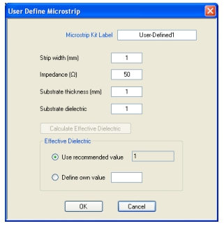
USER DEFINED MICROSTRIP Dialog Box – User-Defined 1
The dialog box allows the definition of a user-provided microstrip device. The input fields for the calibration parameters are:
• Microstrip Kit Label
• Strip width (mm)
• Impedance (Ohms)
• Substrate thickness (mm)
• Substrate dielectric value
• If this field is cleared, the Calculate Effective Dielectric button is enabled for the fields below.
• Effective dielectric value
• Use a recommended value
• Define a user value
USER DEFINED STANDARD Dialog Box – 2-Port VNAs
The exact title and contents of the dialog box depend on the calibration method and connector types selected. This dialog box displays parametric information for a user-defined connector. For the equivalent dialog box for a standard connector such as a V-connector, see STANDARD INFO Dialog Box – 2-Port VNAs
Previous
• The STANDARD INFO dialog box can be accessed from multiple locations.
• DUT Connector Type = User-Defined 1 (M or F) to User-Defined 32 (M or F)
Navigation
• MAIN | Calibration | CALIBRATION | Calibrate | CALIBRATE | Manual Cal | MANUAL CAL | 2-Port Cal | TWO PORT CAL | Modify Cal Setup | CAL SETUP | Edit Cal Params | TWO PORT CAL SETUP (SOLT/R, Coaxial) | DUT Connector = User-Defined 1 (M) | Standard Info button | USER DEFINED STANDARD Dialog Box
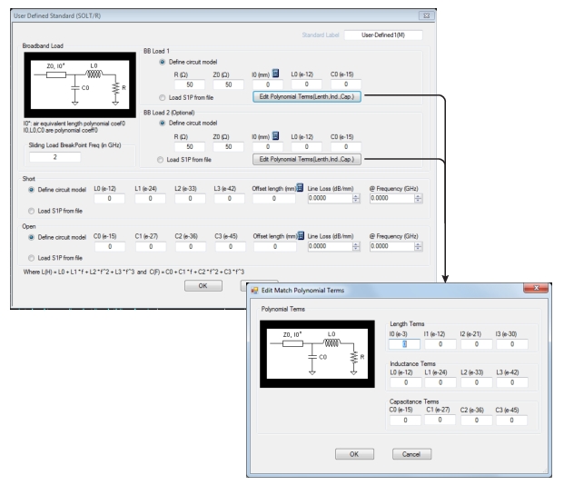
USER DEFINED STANDARD Dialog Box
The USER DEFINED STANDARD dialog box allows the input of the calibration parameters for a user-defined device.
Standard Label
Either leave as the pre-defined label or input a new label for the device.
BB Load 1
Define the broadband load 1 circuit model with the following parameters:
• R (Ohms)
• Z0 (Ohms)
• l0 (mm)
• If required, a link is available to the AIR EQUIVALENT LENGTH CONVERSION dialog box.
• MAIN | Calibration | CALIBRATION | Calibrate | CALIBRATE | Manual Cal | MANUAL CAL | 2-Port Cal | TWO PORT CAL | Modify Cal Setup | CAL SETUP | Cal Method = Broadband Cal (SOLT/R-SSST/R) | Line Type = Coaxial | Edit Cal Params | FULL TWO PORT CAL SETUP BROADBAND CAL, MERGED SOLT-SSST/SOLR-SSSR) Dialog Box | DUT Connector = User-Defined (M) | Standard Info | USER DEFINED STANDARD INFO (Broadband)
Standard Info (Broadband Cal) Dialog for User-Defined Connector
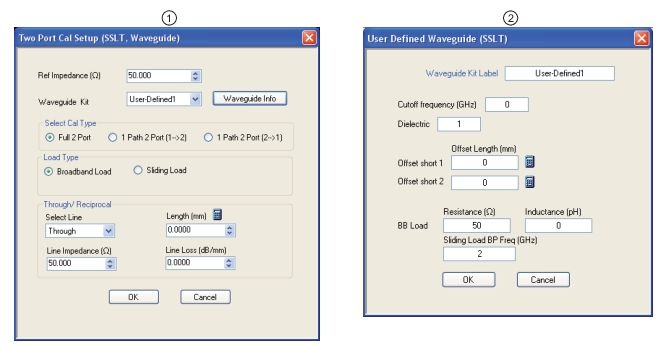
USER DEFINED WAVEGUIDE Dialog Box – 2-Port VNAs
This dialog box displays parametric information for a user-defined waveguide. For the equivalent dialog box for a standard waveguide kit, see WAVEGUIDE INFO Dialog Box – 2-Port VNAs.
Previous
• The USER DEFINED WAVEGUIDE dialog box can be accessed from multiple locations when Line Type is set to Waveguide.
• TWO PORT CAL SETUP (SSLT, Waveguide) Dialog Box
Prerequisites
• Line Type = Waveguide
• DUT Connector Type = User-Defined 1 to User-Defined 32
Navigation
• MAIN | Calibration | CALIBRATION | Calibrate | CALIBRATE | Manual Cal | MANUAL CAL | 2-Port Cal | TWO PORT CAL | Modify Cal Setup | CAL SETUP | Cal Method = SSLT | Line Type = Waveguide | Edit Cal Params | TWO PORT CAL SETUP (SSLT, Waveguide) | Waveguide Kit = User-Defined 1 | Waveguide Info button | USER DEFINED WAVEGUIDE Dialog Box
USER DEFINED WAVEGUIDE Dialog Box
Description
The USER DEFINED WAVEGUIDE dialog box allows the input of the calibration parameters for a user-defined device.
Standard Label
Either leave as the pre-defined label or input a new label for the device.
Cutoff Frequency and Dielectric
• Cutoff frequency (GHz)
• Dielectric value
Broadband Load Definition
Define the broadband load with the following parameters:
• Resistance (Ohms)
• Inductance (pH)
• Sliding Load Break Point Frequency (GHz)
Short Definition
• Offset length (mm)
• If required, a link is available to the AIR EQUIVALENT LENGTH CONVERSION dialog box.
• DUT Connector Type = User-Defined 1 to User-Defined 32
Navigation
• MAIN | Calibration | CALIBRATION | Calibrate | CALIBRATE | Manual Cal | MANUAL CAL | Refl. Freq. Response | REFL. RESPONSE | Modify Cal Setup | CAL SETUP | Cal Method = SOLT/SOLR | Line Type = Waveguide | Edit Cal Params | REFLECION FREQ. RESPONSE CAL SETUP SOLT/R, Waveguide) | Select Cal Component = Short | Waveguide Info button | USER DEFINED WAVEGUIDE SHORT Dialog Box
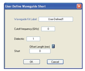
USER DEFINED WAVEGUIDE SHORT Dialog Box – 2-Port VNAs
Description
The USER DEFINED WAVEGUIDE SHORT dialog box provides for the following parameter definitions:
Waveguide Kit Label
• Either keep the default User-Defined label or enter a unique name.
Cutoff Frequency (GHz)
• Enter the cutoff frequency in GHz.
Dielectric Value
• Enter a dielectric value.
Short Offset Length (mm)
• Enter a short offset length in mm.
• If needed, select the Calculator icon to link to the AIR EQUIVALENT LENGTHCONVERSION dialog box.
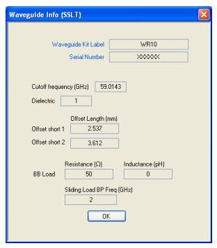
This read-only dialog box displays parametric information for a standard waveguide kit. For the equivalent dialog box for a user-defined waveguide, see USER DEFINED WAVEGUIDE Dialog Box – 2-Port VNAs.
Previous
• The WAVEGUIDE INFO dialog box can be accessed from multiple locations when Line Type is set to Waveguide.
• TWO PORT CAL SETUP (SSLT, WAVEGUIDE) Dialog Box
Prerequisites
• Line Type = Waveguide
• DUT Connector Type = User-Defined 1 to User-Defined 32
Navigation
• MAIN | Calibration | CALIBRATION | Calibrate | CALIBRATE | Manual Cal | MANUAL CAL | 2-Port Cal | TWO PORT CAL | Modify Cal Setup | CAL SETUP | Cal Method = SSLT | Line Type = Waveguide | Edit Cal Params | TWO PORT CAL SETUP (SSLT, Waveguide) | Waveguide Kit = WR10, WR12, or WR15 | Waveguide Info button | USER DEFINED WAVEGUIDE Dialog Box
WAVEGUIDE INFO Dialog Box
Description
The read-only WAVEGUIDE INFO dialog box provides the calibration parameters for the WR10, WR12, and WR15 waveguide kits.