Manual Calibration – Reflection Frequency Response Calibration – 2-Port VNAs
Note
The appearance and button availability of the calibration menus depends on the settings established in the CAL SETUP, CAL METHOD, LINE TYPE menus and in the associated dialog boxes that appear from the Edit Cal Params button.
Menu Name
• REFL. RESPONSE
Button Name
• Reflection Freq. Response
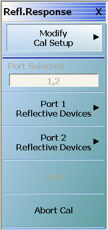
REFL. RESPONSE Menu – 2-Port VNAs
Full Name
Reflection Response
The exact composition of the menu depends on the settings made on the CAL SETUP, CAL METHOD, and LINE TYPE menus and on the resultant REFLECTION FREQUENCY REPONSE CAL SETUP dialog box. A representative menu is shown below. There is one example procedure of a REFL. RESPONSE calibration in this chapter.
• MAIN | Calibration | CALIBRATION | Calibrate | CALIBRATE | Manual Cal | MANUAL CAL | Reflection Freq. Response | REFL. RESPONSE
REFL. RESPONSE Menu – Refl. Freq. Resp. Cal. – 2-Port VNAs – Typical example (1 of 2)
Modify Cal Setup
Select displays the CAL SETUP menu where the Edit Cal Params button provides access to the REFLECTION FREQ. RESPONSE CAL SETUP dialog box for the selected calibration method and line type.
Read-only display of the ports selected for the pending calibration.
Completion Menu Buttons
For this example menu, the Port 1 Reflective Devices, Port 2 Reflective Devices, Thru/Recip, and Isolation (Optional) buttons link to completion submenus where additional calibration procedures are performed.
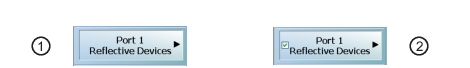
For example, the Port 1 Reflective Devices button (shown below at #1) links to the REFL. DEVICES PORT 1 submenu. As each procedure is completed, the submenu button is marked with a completion checkmark. When all the procedures on the submenu are completed, use the Back button to return to the REFL. RESPONSE menu.
The Port 1 Reflective Devices button (shown above at #2) is now marked with a completion checkmark.
Port 1 Reflective Devices
When selected, the REFL. DEVICES PORT 1 menu appears where each button represents a completion task. When ready for the task, click the button, and the instrument performs the calibration. When the calibration task is successfully completed, the button is marked with a completion checkmark. When all tasks are completed on the menu, return to the REFL. RESPONSE menu.
Port 2 Reflective Devices
When selected, displays the REFL. DEVICES PORT 2 menu where each button represents a completion task. When ready for the task, click the button, and the instrument performs the calibration. When the calibration task is successfully completed, the button is marked with a completion checkmark. When all tasks are completed on the menu, return to the REFL. RESPONSE menu.
Done
This button is unavailable until all calibration tasks have been successfully completed. When available, select the button to return to the CALIBRATION menu when the Cal Status is set to ON.
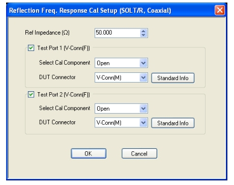
• MAIN | Calibration | CALIBRATION | Calibrate | CALIBRATE | Manual Cal | MANUAL CAL | Reflection Freq Response | REFL. RESPONSE | Modify Cal Setup | CAL SETUP | Edit Cal Params | REFLECTION FREQ REPONSE CAL SETUP (SOLT/R, Coaxial) Dialog Box
REFL. FREQ. RESP. CAL SETUP (SOLT/R, Coaxial) Dialog Box
REFLECTION FREQUENCY RESPONSE CALIBRATION SETUP Dialog Box
Reference Impedance
Input the reference impedance.
• Input field defaulted to 50 Ohms.
• Any numerical value accepted, although input values < 0.01 Ohms are converted to 0.01 Ohms.
Test Port Selection
Select any combination:
• Test Port 1
• Test Port 2
• Test Port 1 and Test Port 2
Test Port 1 Select Cal Component
Select either: Open or Short
Test Port 1 DUT Connector
Select the Test Port 1 Connector type from the pull down menu with options of:
• 0.8 mm-Conn (M)
• 0.8 mm-Conn (F)
• W1-Conn (M)
• W1-Conn (F)
• V-Conn (M)
• V-Conn (F)
• K-Conn (M)
• K-Conn (F)
• 2.4 mm (M)
• 2.4 mm (F)
• GPC-3.5 (M)
• GPC-3.5 (F)
• SMA (M)
• SMA (F)
• N-Conn (M)
• N-Conn (F)
• N-Conn (75) (M)
• N-Conn (75) (F)
• GPC-7
• 7/16 (M)
• 7/16 (F)
• TNC (F) (Kit from Maury Microwave)
• TNC (F) (Kit from Maury Microwave)
• User-Defined 1 (M) through User-Defined 32 (M)
• User-Defined 1 (F) through User-Defined 32 (F)
Test Port 1 Connector Standard Info Button
Select displays the STANDARD INFO (SOLT/R) STANDARD LABEL (V-Conn M) Dialog Box. Note that the name of this dialog changes depending on the selected Cal Method and DUT Connector.
Test Port 2 Select Cal Component
Select either:
• Open
• Short
Test Port 2 DUT Connector
Select the Test Port 2 Connector type from the pull down menu. The options are the same as those for Test Port 1.
Test Port 2 Connector Standard Info Button
Select displays the STANDARD INFO (SOLT/R) STANDARD LABEL (V-Conn M) Dialog Box. Note that the name of this dialog changes depending on the selected Cal Method and DUT Connector.
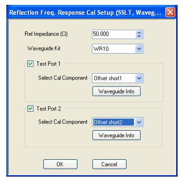
REFLECTION FREQ. RESPONSE CAL SETUP (SSLT, Waveguide) Dialog Box
Select displays the WAVEGUIDE KIT or USER DEFINED WAVEGUIDE dialog box for the selected waveguide as described above.
Refl. Freq. Resp. Calibration Setup Dialog Box Summary
The table below summarizes the available fields and controls in other reflection frequency response calibration setup dialog boxes. To view each dialog box, set the CAL METHOD and LINE TYPE menus to the appropriate settings, and then select the Edit Cal Params button.
Manual Calibration – Reflection Frequency Response Cal Setup – 2-Port VNAs (1 of 3)
Test Port 1 and Test Port 2 controls are the same. Port must be selected to enable controls.
Test Port Cal Component: Offset Short 1, Offset Short 2
Test Port DUT Connector: For each selected test port, select one of the following connectors: 0.8 mm-Conn (M), 0.8 mm-Conn (F), W1-Conn (M), W1-Conn (F), User-Defined 1 (M) through User-Defined 32 (M), User-Defined 1 (F) through User-Defined 32 (F)
Test Port Connector Standard Info Button: For each DUT port connector, displays the info dialog box for the selected connector.
Test Port 1 and Test Port 2 controls are the same. Port must be selected to enable controls.
Test Port Cal Component: Offset Short 1, Offset Short 2, Offset Short 2
Test Port DUT Connector: For each selected test port, select one of the following connectors: 0.8 mm-Conn (M), 0.8 mm-Conn (F), W1-Conn (M), W1-Conn (F), User-Defined 1 (M) through User-Defined 32 (M), User-Defined 1 (F) through User-Defined 32 (F)
Test Port Connector Standard Info Button: For each DUT port connector, displays the appropriate information dialog box for the selected connector.