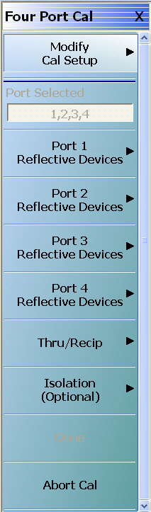
The FOUR PORT CAL Setup menu and its related dialog boxes is used to set the calibration parameters for the four port calibration.
FOUR PORT CAL Menu – 4-Port VNAs
Button Availability
• The exact composition of the menu depends on the settings made on the CAL SETUP, CAL METHOD, and LINE TYPE menus and on the resultant FULL FOUR PORT CAL SETUP dialog box.
• The example procedures at the end of this chapter show examples of various FOUR PORT CAL menus.
• MAIN | Calibration | CALIBRATION | Calibrate | CALIBRATE | Manual Cal | MANUAL CAL | 4-Port Cal | FOUR PORT CAL
FOUR PORT CAL Menu – 4-Port VNAs – Typical Example (1 of 3)
Modify Cal Setup
Select displays the CAL SETUP menu where the Edit Cal Params button provides access to the FULL FOUR PORT CAL SETUP dialog box for the selected calibration method and line type.
Port Selected: Read-only display of the ports selected for the pending calibration.
Completion Menu Buttons
For this example menu, the Port 1 Reflective Devices to the Isolation (Optional) buttons link to completion submenus where additional calibration procedures are performed.
For example, the Port 1 Reflective Devices button (shown below at #1) links to the REFL. DEVICES PORT 1 submenu. As each procedure is completed, the submenu button is marked with a completion checkmark.
When all the procedures on the submenu are completed, use the Back button to return to the FOUR PORT CAL menu. The Port 1 Reflective Devices button (shown below at #2) is now marked with a completion checkmark.
Port 1 Reflective Devices
Select displays the REFL. DEVICES PORT 1 submenu. When all procedures are complete, select the Back button to return to the FOUR PORT CAL menu where this button is now marked with a completion checkmark.
Select displays the REFL. DEVICES PORT 2 submenu. When all procedures are complete, select the Back button to return to the FOUR PORT CAL menu where this button is now marked with a completion checkmark.
Port 3 Reflective Devices
Select displays the REFL. DEVICES PORT 3 submenu. When all procedures are complete, select the Back button to return to the FOUR PORT CAL menu where this button is now marked with a completion checkmark.
Port 4 Reflective Devices
Select displays the REFL. DEVICES PORT 4 submenu. When all procedures are complete, select the Back button to return to the FOUR PORT CAL menu where this button is now marked with a completion checkmark.
Thru/Recip
Select displays the THRU/RECIP submenu. When all procedures are complete, select the Back button to return to the FOUR PORT CAL menu where this button is now marked with a completion checkmark.
If required, select displays the ISOLATION submenu. When all procedures are complete, select the Back button to return to the FOUR PORT CAL menu where this button is now marked with a completion checkmark.
This button is unavailable until all measurements for a particular cal setup is completed. When it is available and is clicked, it returns the user to the CALIBRATION menu where the Cal Status button is set to ON.
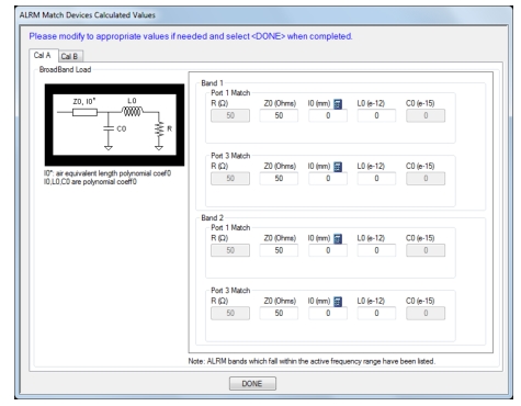
However, when LRL/LRM is selected for 4-Port Cal, and the setup procedure has been completed for the devices, the ALRM Match Devices Calculated Values dialog appears to allow for further modifications.
ALRM Match Devices Calculated Values Dialog for Cal A Match Devices
When ALRM is selected for 4-Port Cal, and the setup procedure has been completed for the devices in theFOUR PORT CAL Menu – 4-Port VNAs, this dialog appears when Done is clicked on the menu.
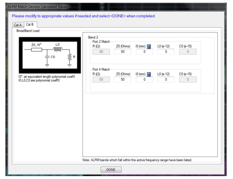
ALRM Match Devices Calculated Values Dialog for Cal B Match Devices
When ALRM is selected for 4-Port Cal, and the setup procedure has been completed for the devices in theFOUR PORT CAL Menu – 4-Port VNAs, this dialog appears when Done is clicked on the menu.
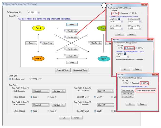
FULL FOUR PORT CAL SETUP (SOLT/R, Coaxial) Dialog Box
• MAIN | Calibration | CALIBRATION | Calibrate | CALIBRATE | Manual Cal | MANUAL CAL | 4-Port Cal | FOUR PORT CAL | Modify Cal Setup | CAL SETUP | Cal Method = SOLT/SOLR | Line Type = Coaxial | Edit Cal Params | FULL FOUR PORT CAL SETUP (SOLT/R, Coaxial) Dialog Box
FULL FOUR PORT CAL SETUP (SOLT/R, Coaxial) Dialog Box
1. Through selected allows user entries for length, line impedance, line loss, and frequency. Reciprocal selected allows user entry for length. S2P Thru selected provides buttons for loading, viewing, and characterization (to generate S2P files).
Reference Impedance
Input the reference impedance.
• Input field defaulted to 50 Ohms.
• Any numerical value accepted, although input values < 0.01 Ohms are converted to 0.01 Ohms.
Select Through Area
Select any combination of throughs as long as three are selected. For a 4-port calibration, the following port pairs are available:
• Thru 1-2
• Thru 1-3
• Thru 1-4
• Thru 2-3
• Thru 2-4
• Thru 3.4
Thru Buttons
Each of the Throughs above enables a Thru Info button that displays the THRU INFO dialog box allowing configuration of each through. A calculator icon in the THRU INFO dialog box allows access to the AIR EQUIVALENT LENGTH CALCULATOR dialog box.
Each of the Swap buttons allows the associated ports to be swapped, so that the port configuration diagram better matches the physical setup.
Load Type Area
Select from two radio button controlled options:
• Broadband Load
• Sliding Load. If Sliding Load is selected, a message appears in the “Still requires broadband loads below sliding load breakpoint frequency.”
Test Port 1 Connector Type Area
Select the DUT Connector Type from a drop-down menu list with options of:
• 0.8 mm-Conn (M)
• 0.8 mm-Conn (F)
• W1-Conn (M)
• W1-Conn (F)
• V-Conn (M)
• V-Conn (F)
• K-Conn (M)
• K-Conn (F)
• GPC-3.5 (M)
• GPC-3.5 (F)
• SMA (M)
• SMA (F)
• N-Conn (M)
• N-Conn (F)
• N-Conn (75) (M)
• N-Conn (75) (F)
• GPC-7
• 7/16 (M)
• 7/16 (F)
• TNC (M) (Kit from Maury Microwave)
• TNC (F) (Kit from Maury Microwave)
• User-Defined1 (M) through User-Defined32 (M)
• User-Defined1 (F) through User-Defined32 (F)
Test Port 1 Connector Standard Info Button
Select displays the STANDARD INFO dialog box for the selected connector and calibration method that displays the connector calibration coefficients. The dialog box contents depend on the selected connector, Cal Method, and Line Type. The example here shows a typical standard information dialog box.
Test Port 2, Test Port 3, and Test Port 4 Connector Type Area
Identical function as with the Test Port 1 Connector Area above. Select the DUT Connector Type from a drop-down menu list.
Test Port 2, Test Port 3, and Test Port 4 Connector Standard Info Button
Identical function as with the Test Port 1 Connector Standard Info Button above. Select displays the STANDARD INFO dialog box for the selected DUT Connector.
Test Port 2, Test Port 3, and Test Port 4 Select BB Load Area
Identical function as with the Test Port 1 Select BB Load Area above. Select between Load 1 and Load 2.
OK / Cancel
Click OK to accept the changes and return to the CAL SETUP menu.
Click Cancel to abandon any changes and return to the CAL SETUP menu.
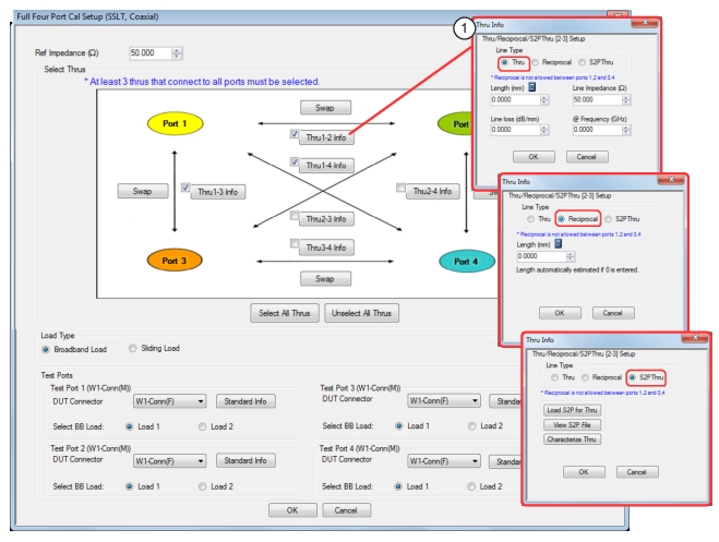
FULL FOUR PORT CAL SETUP (SSLT, Coaxial) Dialog Box
• MAIN | Calibration | CALIBRATION | Calibrate | CALIBRATE | Manual Cal | MANUAL CAL | 4-Port Cal | FOUR PORT CAL | Modify Cal Setup | CAL SETUP | Cal Method = SSLT | Line Type = Coaxial | Edit Cal Params | FULL FOUR PORT CAL SETUP (SSLT, Coaxial) Dialog Box
FULL FOUR PORT CAL SETUP (SSLT, Coaxial) Dialog Box
1. Through selected allows user entries for length, line impedance, line loss, and frequency. Reciprocal selected allows user entry for length. S2P Thru selected provides buttons for loading, viewing, and characterization (to generate S2P files).
Reference Impedance
Input the reference impedance.
• Input field defaulted to 50 Ohms.
• Any numerical value accepted, although input values < 0.01 Ohms are converted to 0.01 Ohms.
Select Throughs
Select any combination of throughs as long as three are selected. For a 4-port calibration, the following port pairs are available:
• Thru 1-2
• Thru 1-3
• Thru 1-4
• Thru 2-3
• Thru 2-4
• Thru 3-4
Swap Buttons
Each of the Swap buttons allows the associated ports to be swapped, so that the port configuration diagram better matches the physical setup.
Thru Buttons
Each of the throughs above enables a Thru Info button that displays the THRU INFO dialog box allowing configuration of each through. A calculator icon in the THRU INFO dialog box allows access to the AIR EQUIVALENT LENGTH CALCULATOR dialog box.
• Sliding Load. If Sliding Load is selected, a message appears in the “Still requires broadband loads below sliding load breakpoint frequency.”
Test Port 1 Connector Type
Select the DUT Connector Type from a drop-down menu list with options of:
• 0.8 mm-Conn (M)
• 0.8 mm-Conn (F)
• W1-Conn (M)
• W1-Conn (F)
• User-Defined1 (M) through User-Defined32 (M)
• User-Defined1 (F) through User-Defined32 (F)
Test Port 1 Connector Standard Info Button
Select displays the STANDARD INFO dialog box for the selected connector and calibration method that displays the connector calibration coefficients. The dialog box contents depend on the selected connector, Cal Method, and Line Type. The example here shows a typical standard information dialog box.
Test Port 2, Test Port 3, and Test Port 4 Connector Type
Identical function as with the Test Port 1 Connector above. Select the DUT Connector Type from a drop-down menu list.
Test Port 2, Test Port 3, and Test Port 4 Connector Standard Info Button
Identical function as with the Test Port 1 Connector Standard Info Button above. Select displays the STANDARD INFO dialog box for the selected DUT Connector.
Test Port 2, Test Port 3, and Test Port 4 Select BB Load
Identical function as with the Test Port 1 Select BB Load above. Select between Load 1 and Load 2.
OK / Cancel
Click OK to accept the changes and return to the CAL SETUP menu.
Click Cancel to abandon any changes and return to the CAL SETUP menu.
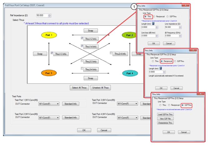
FULL FOUR PORT CAL SETUP (SSST, Coaxial) Dialog Box
• This dialog box is available from multiple menus.
• MAIN | Calibration | CALIBRATION | Calibrate | CALIBRATE | Manual Cal | MANUAL CAL | 4-Port Cal | FOUR PORT CAL | Modify Cal Setup | CAL SETUP | Cal Method = SSST | Line Type = Coaxial | Edit Cal Params | FULL FOUR PORT CAL SETUP (SSST, Coaxial) Dialog Box
FULL FOUR PORT CAL SETUP (SSST, Coaxial) Dialog Box
1. Through selected allows user entries for length, line impedance, line loss, and frequency. Reciprocal selected allows user entry for length. S2P Thru selected provides buttons for loading, viewing, and characterization (to generate S2P files).
Reference Impedance
Input the reference impedance.
• Input field defaulted to 50 Ohms.
• Any numerical value accepted, although input values < 0.01 Ohms are converted to 0.01 Ohms.
Select Throughs
Select any combination of throughs as long as three are selected. For a 4-port calibration, the following port pairs are available:
• Thru 1-2
• Thru 1-3
• Thru 1-4
• Thru 2-3
• Thru 2-4
• Thru 3-4
Swap Buttons
Each of the Swap buttons allows the associated ports to be swapped, so that the port configuration diagram better matches the physical setup.
Thru Info Buttons
Each of the throughs above enables a Thru Info button that displays the THRU INFO dialog box allowing configuration of each through. A calculator icon in the THRU INFO dialog box allows access to the AIR EQUIVALENT LENGTH CALCULATOR dialog box.
Select the DUT Connector Type from a drop-down menu list with options of:
• 0.8 mm-Conn (M)
• 0.8 mm-Conn (F)
• W1-Conn (M)
• W1-Conn (F)
• User-Defined1 (M) through User-Defined32 (M)
• User-Defined1 (F) through User-Defined32 (F)
Test Port 1 Connector Standard Info Button
Select displays the STANDARD INFO dialog box for the selected connector and calibration method that displays the connector calibration coefficients. The dialog box contents depend on the selected connector, Cal Method, and Line Type. The example here shows a typical standard information dialog box.
Test Port 2, Test Port 3, and Test Port 4 Connector Type
Identical function as with the Test Port 1 Connector above. Select the DUT Connector Type from a drop-down menu list.
Test Port 2, Test Port 3, and Test Port 4 Connector Standard Info Button
Identical function as with the Test Port 1 Connector Standard Info Button above. Select displays the STANDARD INFO dialog box for the selected DUT Connector.
OK / Cancel
Click OK to accept the changes and return to the CAL SETUP menu.
Click Cancel to abandon any changes and return to the CAL SETUP menu.
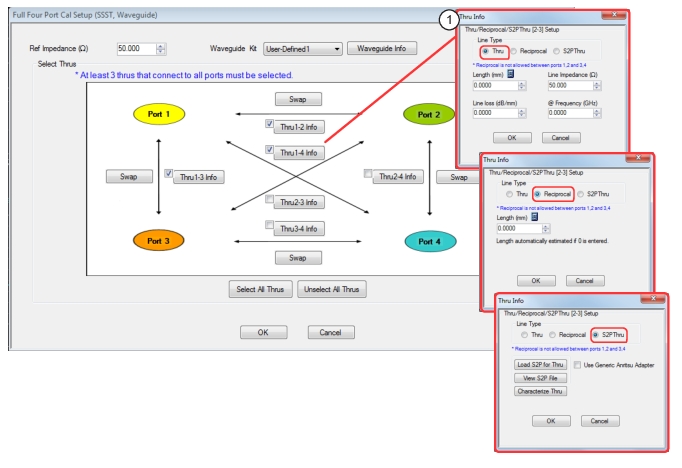
FULL FOUR PORT CAL SETUP (SSST, Waveguide) Dialog Box
• This dialog box is available from multiple menus.
• MAIN | Calibration | CALIBRATION | Calibrate | CALIBRATE | Manual Cal | MANUAL CAL | 4-Port Cal | FOUR PORT CAL | Modify Cal Setup | CAL SETUP | Cal Method = SSST | Line Type = Waveguide | Edit Cal Params | FULL FOUR PORT CAL SETUP (SSST, Waveguide) Dialog Box
FULL FOUR PORT CAL SETUP (SSST, Waveguide) Dialog Box
1. Through selected allows user entries for length, line impedance, line loss, and frequency. Reciprocal selected allows user entry for length. S2P Thru selected provides buttons for loading, viewing, and characterization (to generate S2P files).
Reference Impedance
Input the reference impedance.
• Input field defaulted to 50 Ohms.
• Any numerical value accepted, although input values < 0.01 Ohms are converted to 0.01 Ohms.
Waveguide Kit
Select the Waveguide Kit from a drop-down menu list with options of:
• User-Defined1 through User-Defined32
Select Throughs
Select any combination of throughs as long as three are selected that connect to all ports. For a 4-port calibration, the following port pairs are available:
• Thru 1-2
• Thru 1-3
• Thru 1-4
• Thru 2-3
• Thru 2-4
• Thru 3.4
Swap Buttons
Each of the Swap buttons allows the associated ports to be swapped, so that the port configuration diagram better matches the physical setup.
Thru Buttons
As each through is selected, it enables a Thru Info button that displays the THRU INFO configuration dialog box for the selected port pair. A calculator icon in the THRU INFO dialog box allows access to the AIR EQUIVALENT LENGTH CALCULATOR dialog box.
• Cal Method = Broadband Cal (SOLT/R-SSST/R) – Appears only with VNA in Broadband Mode (3739)
• Line Type = Coaxial
Navigation
• MAIN | Calibration | CALIBRATION | Calibrate | CALIBRATE | Manual Cal | MANUAL CAL | 4-Port Cal | FOUR PORT CAL | Modify Cal Setup | CAL SETUP | Cal Method = Broadband Cal (SOLT/R-SSST/R) | Line Type = Coaxial | Edit Cal Params | FULL FOUR PORT CAL SETUP BROADBAND CAL, MERGED SOLT-SSST/SOLR-SSSR) Dialog Box
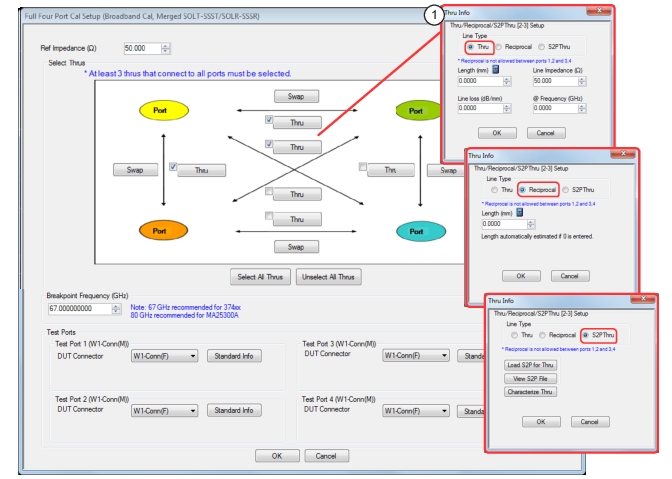
FULL FOUR PORT CAL SETUP Broadband Cal, Merged (SOLT/SOLR-SSST/SSSR) Dialog Box
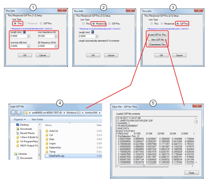
1. Through selected allows user entries for length, line impedance, line loss, and frequency. Reciprocal selected allows user entry for length. S2P Thru selected provides buttons for loading, viewing, and characterization (to generate S2P files).
1. Thru Info Dialog – Line Type Thru selected, allowing configuration of Thru
2. Thru Info Dialog – Line Type S2P Thru selected, allowing loading, viewing and generation of S2P files
3. File Load Dialog
4. View S2P File contents window
Reference Impedance
Input the reference impedance.
• Input field defaulted to 50 Ohms.
• Any numerical value accepted, although input values < 0.01 Ohms are converted to 0.01 Ohms.
Select Through Area
Select any combination of throughs as long as three are selected. For a 4-port calibration, the following port pairs are available:
• Thru 1-2
• Thru 2-3
• Thru 1-3
• Thru 2-4
• Thru 1-4
• Thru 3.4
Thru Buttons
Each of the Throughs above enables a Thru Info button that displays the THRU INFO dialog box allowing configuration of each through, or loading of an S2P file. A calculator icon in the THRU INFO dialog box allows access to the AIR EQUIVALENT LENGTH CALCULATOR dialog box.
Each of the Swap buttons allows the associated ports to be swapped, so that the port configuration diagram better matches the physical setup.
Breakpoint Frequency
• 67 GHz is recommended for the 3656 (1 mm) calibration kit.
• 80 GHz is recommended for the 3659 (0.8 mm) calibration kit.
• In this combined calibration, the breakpoint frequency defines the frequency above which the SSS algorithm will be used (and SOL will be used for the frequencies at or below the breakpoint). Default values are based on Anritsu calibration kits and are optimal for those components.
Test Port 1 Connector Type Area
Select the DUT Connector Type from a drop-down menu list with options of:
• 0.8 mm-Conn (M)
• 0.8 mm-Conn (F)
• W1-Conn (M)
• W1-Conn (F)
• User-Defined1 (M) through User-Defined32 (M)
• User-Defined1 (F) through User-Defined32 (F)
Test Port 1 Connector Standard Info Button
Select displays the STANDARD INFO dialog box for the selected connector and calibration method that displays the connector calibration coefficients. The dialog box contents depend on the selected connector, Cal Method, and Line Type. The following link shows a typical standard information dialog box for broadband cal.
Test Port 2, Test Port 3, and Test Port 4 Connector Type Area
Identical function as with the Test Port 1 Connector Area above. Select the DUT Connector Type from a drop-down menu list.
Test Port 2, Test Port 3, and Test Port 4 Connector Standard Info Button
Identical function as with the Test Port 1 Connector Standard Info Button above. Select displays the STANDARD INFO dialog box for the selected DUT Connector.
OK / Cancel
Click OK to accept the changes or Cancel to abandon any changes and return to the CAL SETUP menu.
FULL FOUR PORT CAL SETUP (TRL/TRM, Coaxial) Dialog Box
• VNA Mode = 4-Port Mode; Cal Method = TRL/TRM; Line Type = Coaxial
Navigation
• MAIN | Calibration | CALIBRATION | Calibrate | CALIBRATE | Manual Cal | MANUAL CAL | 4-Port Cal | FOUR PORT CAL | Modify Cal Setup | CAL SETUP | Cal Method = TRL/TRM | Line Type = Coaxial | Edit Cal Params | FULL FOUR PORT CAL SETUP (TRL/TRM, Coaxial) Dialog Box
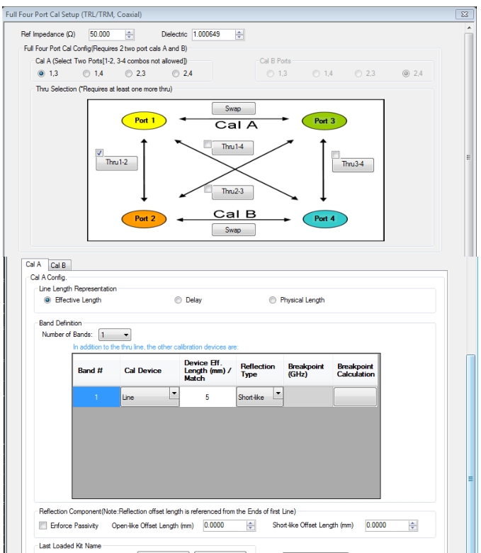
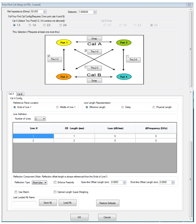
FOUR PORT CAL SETUP (TRL/TRM, Coaxial) Dialog Box
Overview
The dialog box provides common areas for Reference Impedance, Full Four Port Calibration Configuration, and Thru Selection. Below this common section are two tabbed dialog areas for Cal A and Cal B.
Full Four Port Cal Configuration
Requires two 2-port calibrations as Cal A and Cal B, configured below.
Reference Impedance
• Input field defaulted to 50 Ohms.
• Any numerical value accepted, although input values < 0.01 Ohms are converted to 0.01 Ohms.
Dielectric
Enter a value if different than the default.
Cal A Ports
Allows selection of the calibration A port pair. Combinations of ports 1-2 and ports 3-4 are not allowed.
• Port 1, 3
• Port 1, 4
• Port 2, 3
• Port 2, 4
Cal B Ports
This area is read-only and defined by the port pair choice for Cal A.
• If Cal A = Ports 1, 3, then Cal B = Ports 2, 4
• If Cal A = Ports 1, 4, then Cal B = Ports 2, 3
• If Cal A = Ports 2, 3, then Cal B = Ports 1, 4
• If Cal A = Ports 2, 4, then Cal B = Ports 1, 3
Thru Selection
Any combination of Throughs may be selected as long as least one additional through is selected from:
• Thru 1-2
• Thru 1-3
• Thru 1-4
• Thru 3-4
Swap Buttons
Each of the Swap buttons allows the associated ports to be swapped, so that the port configuration diagram better matches the physical setup.
Cal A / Cal B Tabs
Access the Cal A or Cal B functions and controls by selecting either the Cal A or Cal B tab.
Line Length Representation
Select from three radio button controlled options:
• Effective Length (the free-space equivalent length)
• Delay
• Physical Length
Band Definition
Select one to five bands from the drop-down menu.
• Number of Bands = 1. Only the Band 1 Definition and editable parameters appear.
• Number of Bands = 2. The Band 2 Definition and editable parameters appear.
• Number of Bands = 3. The Band 3 Definition and editable parameters appear.
• Number of Bands = 4. The Band 4 Definition and editable parameters appear.
• Number of Bands = 5. The Band 5 Definition and editable parameters appear.
Band Parameter Definitions
• Cal Device
• Line
• Match
• Device Effective Length (mm) / Match
• Line: Enter device effective length for each band
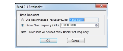
• Enter a breakpoint frequency for Bands 2–5. (This area only active for band 2–5.)
• Breakpoint Calculation
• Select to Calculate a breakpoint frequency for band 2:
Reflection Component
• Enforce Passivity – Forces the reflection value to be passive at an intermediate step in the calibration, which rescales the reflection tracking terms.
• Enter Open-like and/or Short-like offset length
Last Loaded Kit Name, Save Kit, Load Kit, Restore Defaults
• Last Loaded Kit Name – Loaded kit name appears in the field. The name can be edited in this field and then saved as another kit.
• Save Kit saves the present cal setup.
• Load Kit loads a previously saved cal setup.
• Restore Defaults loads the instrument default values for the Cal Setup.
OK/Cancel
• OK and Cancel returns user to the CAL SETUP menu.
FULL FOUR PORT CAL SETUP (LRL/LRM, Coaxial) Dialog Box
• VNA Mode = 4-Port Mode; Cal Method = LRL/LRM; Line Type = Coaxial
Navigation
• MAIN | Calibration | CALIBRATION | Calibrate | CALIBRATE | Manual Cal | MANUAL CAL | 4-Port Cal | FOUR PORT CAL | Modify Cal Setup | CAL SETUP | Cal Method = LRL/LRM | Line Type = Coaxial | Edit Cal Params | FULL FOUR PORT CAL SETUP (LRL/LRM, Coaxial) Dialog Box
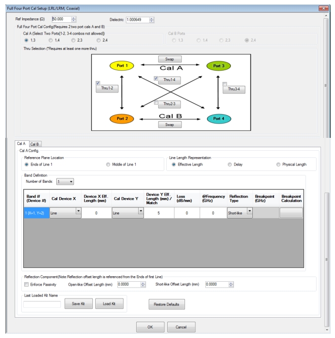
FOUR PORT CAL SETUP (LRL/LRM, Coaxial) Dialog Box (1 of 2)
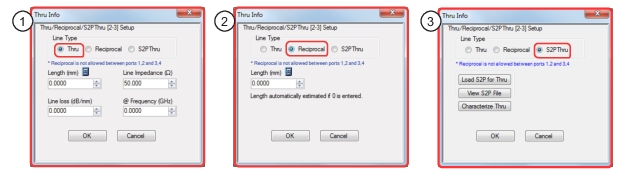
Thru 2-3 Info Example:
1. Through selected allows user entries for length, line impedance, line loss, and frequency.
2. Reciprocal selected allows user entry for length.
3. S2P Thru selected provides buttons for loading, viewing, and characterization (to generate S2P files).
Overview
The dialog box provides common areas for Reference Impedance, Full Four Port Calibration Configuration, and Thru Selection. Below this common section are two tabbed dialog areas for Cal A and Cal B.
Full Four Port Cal Configuration
Requires two 2-port calibrations as Cal A and Cal B, configured below.
Reference Impedance
• Input field defaulted to 50 Ohms.
• Any numerical value accepted, although input values < 0.01 Ohms are converted to 0.01 Ohms.
Dielectric
Enter a value if different than the default.
Cal A Ports
Allows selection of the calibration A port pair. Combinations of ports 1-2 and ports 3-4 are not allowed.
• Port 1, 3
• Port 1, 4
• Port 2, 3
• Port 2, 4
Cal B Ports
This area is read-only and defined by the port pair choice for Cal A.
• If Cal A = Ports 1, 3, then Cal B = Ports 2, 4
• If Cal A = Ports 1, 4, then Cal B = Ports 2, 3
• If Cal A = Ports 2, 3, then Cal B = Ports 1, 4
• If Cal A = Ports 2, 4, then Cal B = Ports 1, 3
Thru Selection
Any combination of Throughs may be selected as long as least one additional through is selected from:
• Thru 1-2
• Thru 1-3
• Thru 1-4
• Thru 3-4
Swap Buttons
Each of the Swap buttons allows the associated ports to be swapped, so that the port configuration diagram better matches the physical setup.
Cal A / Cal B Tabs
Access the Cal A or Cal B functions and controls by selecting either the Cal A or Cal B tab.
Reference Plane Location
Select from two radio button controlled options:
• Ends of Line 1
• Middle of Line 1
Line Length Representation
Select from three radio button controlled options:
• Effective Length (the free-space equivalent length)
• Delay
• Physical Length
Band Definition
Select one to five bands from the drop-down menu.
• Number of Bands = 1. Only the Band 1 Definition and editable parameters appear.
• Number of Bands = 2. The Band 2 Definition and editable parameters appear.
• Number of Bands = 3. The Band 3 Definition and editable parameters appear.
• Number of Bands = 4. The Band 4 Definition and editable parameters appear.
• Number of Bands = 5. The Band 5 Definition and editable parameters appear.
Band Parameter Definitions
• Band # (Device #)
• Band 1 defines Devices as X = 1 and Y = 2
• Band 2 defines Devices as X = 3 and Y = 4
• Band 3 defines Devices as X = 5 and Y = 6
• Band 4 defines Devices as X = 7 and Y = 8
• Band 5 defines Devices as X = 9 and Y = 10
• Cal Device X
• Band 1 choice is
• Line
• Band 2 choices are
• New Line
• Bnd1 Cal Dev X
• Bnd1 Cal Dev Y
• Band 3 choices are
• New Line
• Bnd1 Cal Dev X
• Bnd1 Cal Dev Y
• Bnd2 Cal Dev X
• Bnd2 Cal Dev Y
• Band 4 choices are
• New Line
• Bnd1 Cal Dev X, Bnd1 Cal Dev Y
• Bnd2 Cal Dev X, Bnd2 Cal Dev Y
• Bnd3 Cal Dev X, Bnd3 Cal Dev Y
• Band 5 choices are
• NewLine
• Bnd1 Cal Dev X, Bnd1 Cal Dev Y
• Bnd2 Cal Dev X, Bnd2 Cal Dev Y
• Bnd3 Cal Dev X, Bnd3 Cal Dev Y
• Bnd4 Cal Dev X, Bnd4 Cal Dev Y
• Device X Length (mm)
• Enter device length for each band
• Cal Device Y
• Select Line or Match for each band.
• Device Y Length (mm)/Match
• Enter device length for each band if Device Y is Line.
• Enter a breakpoint frequency for Bands 2–5. (This area only active for band 2–5.)
• Breakpoint Calculation
• Select to Calculate a breakpoint frequency for band 2:
Reflection Component
• Enforce Passivity – Forces the reflection value to be passive at an intermediate step in the calibration, which rescales the reflection tracking terms.
• Enter Open-like and/or Short-like offset length
Last Loaded Kit Name, Save Kit, Load Kit, Restore Defaults
• Last Loaded Kit Name – Loaded kit name appears in the field. The name can be edited in this field and then saved as another kit.
• Save Kit saves the present cal setup.
• Load Kit loads a previously saved cal setup.
• Restore Defaults loads the instrument default values for the Cal Setup.
OK/Cancel
• OK and Cancel returns user to the CAL SETUP menu.
FULL FOUR PORT CAL SETUP (mTRL, Coaxial) Dialog Box
• VNA Mode = 4-Port Mode; Cal Method = mTRL; Line Type = Coaxial
Navigation
• MAIN | Calibration | CALIBRATION | Calibrate | CALIBRATE | Manual Cal | MANUAL CAL | 4-Port Cal | FOUR PORT CAL | Modify Cal Setup | CAL SETUP | Cal Method = mTRL | Line Type = Coaxial | Edit Cal Params | FULL FOUR PORT CAL SETUP (mTRL, Coaxial) Dialog Box
FOUR PORT CAL SETUP (mTRL, Coaxial) Dialog Box (1 of 2)
Thru 2-3 Info Example:
1. Through selected allows user entries for length, line impedance, line loss, and frequency.
2. Reciprocal selected allows user entry for length.
3. S2P Thru selected provides buttons for loading, viewing, and characterization (to generate S2P files).
Overview
The dialog box provides common areas for Reference Impedance, Dielectric, Full Four Port Calibration Configuration, and Thru Selection. Below this common section are two tabbed dialog areas for Cal A and Cal B.
Full Four Port Cal Configuration
Requires two 2-port calibrations as Cal A and Cal B, configured below.
Reference Impedance
• Input field defaulted to 50 Ohms.
• Any numerical value accepted, although input values < 0.01 Ohms are converted to 0.01 Ohms.
Dielectric
Enter a value if different than the default.
Cal A Ports
Allows selection of the calibration A port pair. Combinations of ports 1-2 and ports 3-4 are not allowed.
• Port 1, 3
• Port 1, 4
• Port 2, 3
• Port 2, 4
Cal B Ports
This area is read-only and defined by the port pair choice for Cal A.
• If Cal A = Ports 1, 3, then Cal B = Ports 2, 4
• If Cal A = Ports 1, 4, then Cal B = Ports 2, 3
• If Cal A = Ports 2, 3, then Cal B = Ports 1, 4
• If Cal A = Ports 2, 4, then Cal B = Ports 1, 3
Thru Selection
Any combination of Thrus may be selected, as long as least one additional through is selected from:
• Thru 1-2
• Thru 1-3
• Thru 1-4
• Thru 3-4
Swap Buttons
Each of the Swap buttons allows the associated ports to be swapped, so that the port configuration diagram better matches the physical setup.
Cal A / Cal B Tabs
Access the Cal A or Cal B functions and controls by selecting either the Cal A or Cal B tab.
Reference Plane Location
Select from two radio button controlled options:
• Ends of Line 1
• Middle of Line 1
Line Length Representation
Select from three radio button controlled options:
• Effective Length (the free-space equivalent length)
• Delay
• Physical Length
Line Definition
Select two to ten line from the drop-down menu.
• Number of Lines = 2. The Lines 1 and 2 editable parameters appear.
• Number of Lines = 3. The Lines 1 through 3 editable parameters appear.
• Number of Lines = 4. The Lines 1 through 4 editable parameters appear.
• ...
• Number of Lines = 10. The Lines 1 through 10 editable parameters appear.
Line Parameter Definitions
• Line #
• Effective Length (mm) (If Effective Length is selected)
• Enter effective length for each line.
• Delay (ps) (If Delay is selected)
• Enter delay for each line.
• Physical Length (mm) (If Physical Length is selected)
• Enter physical length for each line.
• Loss (dB/mm)
• Enter loss for each line.
• @Frequency (GHz)
• Enter frequency for line loss for each line.
Reflection Component
• Select Reflection Type
• Enforce Passivity – Forces the reflection value to be passive at an intermediate step in the calibration, which rescales the reflection tracking terms.
• Enter Open-like and/or Short-like offset length.
• Enables the use of an enhanced weighting scheme during the calibration to further emphasize line pairs that have optimal line length deltas. The use of this feature further de-emphasizes non-optimal pairs and reduces the impact of repeatability differences.
Last Loaded Kit Name, Save Kit, Load Kit, Restore Defaults
• Last Loaded Kit Name – Loaded kit name appears in the field. The name can be edited in this field and then saved as another kit.
• Save Kit saves the present cal setup.
• Load Kit – Click opens window to navigate to a desired existing mTRL cal kit file (.mlcf).
• Restore Defaults loads the instrument default values for the Cal Setup.
OK/Cancel:Returns user to the CAL SETUP menu.
FULL FOUR PORT CAL SETUP (mSSS, Coaxial) Dialog Box
• This dialog box is available from multiple menus.
• MAIN | Calibration | CALIBRATION | Calibrate | CALIBRATE | Manual Cal | MANUAL CAL | 4-Port Cal | FOUR PORT CAL | Modify Cal Setup | CAL SETUP | Cal Method = mSSS | Line Type = Coaxial | Edit Cal Params | FULL FOUR PORT CAL SETUP (mSSS, Coaxial) Dialog Box
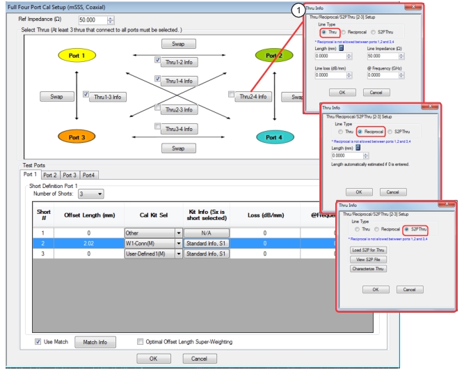
FULL FOUR PORT CAL SETUP (mSSS, Coaxial) Dialog Box
1. Through selected allows user entries for length, line impedance, line loss, and frequency. Reciprocal selected allows user entry for length. S2P Thru selected provides buttons for loading, viewing, and characterization (to generate S2P files).
Reference Impedance
Input the reference impedance.
• Input field defaulted to 50 Ohms.
• Any numerical value accepted, although input values < 0.01 Ohms are converted to 0.01 Ohms.
Select Throughs
Select any combination of throughs as long as three (that are connected to all ports) are selected. For a 4-port calibration, the following port pairs are available:
• Thru 1-2
• Thru 1-3
• Thru 1-4
• Thru 2-3
• Thru 2-4
• Thru 3-4
Swap Buttons
Each of the Swap buttons allows the associated ports to be swapped, so that the port configuration diagram better matches the physical setup.
Thru Info Buttons
Each of the throughs above enables a Thru Info button that displays the THRU INFO dialog box allowing configuration of each through. A calculator icon in the THRU INFO dialog box allows access to the AIR EQUIVALENT LENGTH CALCULATOR dialog box.
Editable if the Cal Kit Sel selected is “Other”; otherwise it will reflect the offset length of the selected short in the cal kit standard (Kit Info column).
Cal Kit Selection
Select the DUT Connector Type from a drop-down menu list with options of:
• Other
• 0.8 mm-Conn (M)
• 0.8 mm-Conn (F)
• W1-Conn (M)
• W1-Conn (F)
• User-Defined1 (M) through User-Defined32 (M)
• User-Defined1 (F) through User-Defined32 (F)
Kit Info Button
Select displays the STANDARD INFO or USER DEFINED STANDARD dialog box for the selected connector and calibration method that displays the connector calibration coefficients. The dialog box contents depend on the selected connector, Cal Method, and Line Type. The examples show typical standard information dialog boxes.
• Since the STANDARD INFORMATION (mSSS) dialog derives from the SSS calibration kit definition, three shorts are available and the one to be used for the current line in the mSSS table is defined by the Select Short to use field. All of the shorts in the kit can be employed in the mSSS calibration, but each must be assigned to a separate line in the table.
This field (in conjunction with the @Frequency field and the offset length) is used to compute the loss in the short and hence the magnitude of its reflection coefficient. This is mainly relevant for very large offset lengths (> 10 mm) at microwave frequencies or somewhat shorter lengths at millimeter wave frequencies.
@Frequency (GHz)
This field (in conjunction with the loss in dB/mm and the offset length) is used to compute the loss of the offset short (and hence the magnitude of its reflection coefficient) at each frequency. If a non-zero value is entered here, it is treated as the reference frequency fref at which the loss (dB/mm) was defined and the loss at all other frequencies is scaled by sqrt(f/fref). If 0 is entered here, the loss is assumed to be constant with frequency.
Use Match Checkbox
When this box is checked, a match measurement is acquired during the calibration and is used whenever even the collection of offset shorts does not have enough phase separation (value defined within the USER DEFINED MATCH dialog: Electrical line length delta for match use, expressed in degrees). The decision to use the match data is made on a frequency-by-frequency basis. See the MS464XB Calibration and Measurement Guide for more information. This helps increase bandwidth of the calibration, particularly at lower frequencies, if a match standard is available.
When this box is checked, more weight is given to those offset shorts that contribute most to large electrical length deltas and hence to bandwidth of the calibration. More details can be found in the MS464XB Calibration and Measurement Guide. Using this feature can increase the available bandwidth of the calibration, but does reduce immunity to repeatability variances in the setup, so it is not advised in more repeatability challenged scenarios (e.g., fixtures where the short standards are attached by spring force alone).
Port 2, Port 3, and Port 4 Tabs – Short Definition
Identical functions as with the Test Ports: Port 1 Tab above.
OK / Cancel
Click OK to accept the changes and return to the CAL SETUP menu.
Click Cancel to abandon any changes and return to the CAL SETUP menu.
Summary of 4-Port Calibration Setup Dialog Boxes
The table below summarizes the available fields in all available 4-port calibration setup dialog boxes. If the dialog box is described above, a link is provided to that description. To view each dialog box, set the CAL METHOD and LINE TYPE menus to the appropriate settings, and then select the Edit Cal Params button. All dialog boxes are named either “Full Four Port Cal Setup (Cal Method, Line Type)” or “Four Port Cal Setup (Cal Method, Line Type)
4-Port Manual Cal Setup Dialog Box Summary (1 of 10)
Select Throughs: At least 3 throughs that connect to all ports must be selected. Select from Thru 1-2, Thru 1-3, Thru 1-4, Thru 2-3, Thru 2-4, Thru 3-4.
Thru Info buttons: Displays the THRU INFO dialog box for the selected through.
Load Type: Select from Broadband Load or Sliding Load
Test Ports: Port 1, Port 2, Port 3, Port 4.
Test Port DUT Connector: For each selected test port, select one of the following connectors: 0.8 mm-Conn (M), 0.8 mm-Conn (F), W1-Conn (M), W1-Conn (F), V-Conn (M), V-Conn (F), K-Conn (M), K-Conn (F), 2.4 mm (M), 2.4 mm (F), 2.4 mm V (M), 2.4 mm V (F), GPC-3.5 (M), GPC-3.5 (F), SMA (M), SMA (F), N-Conn (M), N-Conn (F), N-Conn (75) (M), N-Conn (75) (F), GPC-7, 7/16 (M), 7/16 (F), TNC (M), TNC (F), User-Defined1 (M) through User-Defined32 (M), User-Defined1 (F) through User-Defined32 (F)
Test Port Connector Standard Info Button: For each DUT port connector, displays the STANDARD INFORMATION or USER-DEFINED dialog box for the selected connector.
Select Throughs: At least 3 throughs that connect to all ports must be selected. Select from Thru 1-2, Thru 1-3, Thru 1-4, Thru 2-3, Thru 2-4, Thru 3-4
Thru Info buttons: Displays the THRU INFO dialog box for the selected through.
Each of the Throughs enables a Thru Info button that displays the THRU INFO dialog box allowing configuration of each through. A calculator icon in the THRU INFO dialog box allows access to the AIR EQUIVALENT LENGTH CALCULATOR dialog box.
67 GHz is recommended for the 3656 (1 mm) calibration kit. 80 GHz is recommended for the 3659 (0.8 mm) calibration kit.
Test Port 1 Connector Type Area
Select the DUT Connector Type from a drop-down menu list with options of:
0.8 mm-Conn (M), 0.8 mm-Conn (F), W1-Conn (M), W1-Conn (F), User-Defined1 (M) through User-Defined32 (M), User-Defined1 (F) through User-Defined32 (F)
Test Port 1 Connector Standard Info Button
Select displays the STANDARD INFO dialog box for the selected connector and calibration method that displays the connector calibration coefficients. The dialog box contents depend on the selected connector, Cal Method, and Line Type. The link below shows an example typical standard information dialog box.
Test Port 2, Test Port 3, and Test Port 4 Connector Type Area
Identical function as with the Test Port 1 Connector Area above. Select the DUT Connector Type from a drop-down menu list.
Test Port 2, Test Port 3, and Test Port 4 Connector Standard Info Button
Identical function as with the Test Port 1 Connector Standard Info Button above. Select displays the STANDARD INFO dialog box for the selected DUT Connector.
OK / Cancel: Click OK to accept changes or Cancel to abandon and return to CAL SETUP.
Cal A and Cal B tabs: The “A” and “B” calibration parameters are selected via a tabbed menu within the dialog box.
Cal A Configuration Parameters:
• Line Length Representation: Effective Length, Delay, Physical Length
• Cal A Number of Bands: 1 through 5
• Cal A Band 1-5 Type: Line, Match; Device Effective Length (mm)/Match; If Device X = Match, Match Info button displays USER DEFINED MATCH DEVICES dialog box for selected calibration kit. USER DEFINED MATCH DEVICES Dialog Box – TRL/TRM
• Reflection Type: Short-like, Open-like.
• Cal A Band Breakpoint: Calculate Recommended Value, Use Recommended Frequency (GHz), Define New Frequency (GHz).
• Cal A Reflection Component: Enforce Passivity
• Cal A Reflection Component: Open-like Length (mm), Short-like Offset Length (mm)
• Last Loaded Kit Name – TRL/TRM/LRL/LRM Cal Kit file name last loaded
• Save Kit – Save calibration kit data to an TRL/TRM/LRL/LRM cal kit file (.lcf)
Cal A and Cal B tabs: The “A” and “B” calibration parameters are selected via a tabbed menu within the dialog box.
Number of Bands: 1 through 5:
• If 1, only Band 1 Device 1 and Band 1 Device 2 controls appear.
• If 2, the above plus Band 2 Device 3 and Band 2 Device 4 controls appear.
• If 3, the above plus Band 3 Device 5 and Band 3 Device 6 controls appear.
• If 4, the above plus Band 4 Device 7 and Band 4 Device 8 controls appear.
• If 5, the above plus Band 5 Device 9 and Band 5 Device 10 controls appear.
Cal A Configuration Parameters:
• Cal A Reference Plane Location: Ends of Line, Middle of Line 1
• Line Length Representation: Effective Length, Delay, Physical Length
• Cal A Number of Bands: 1 through 5
• Cal A Band 1 Device 1 Line: Line Length (mm) or Delay (ps), Line Loss (dB/mm), @ Frequency (GHz)
• Cal A Band 1 Device 2 Type: Line, Match; Use Short-like component, Use Open-like component, Use both; If Device 2 = Match, Match Info button displays USER DEFINED MATCH DEVICES dialog box for selected calibration kit.
• Optimal Length Super-Weighting: Enables the use of an enhanced weighting scheme during the calibration to further emphasize line pairs that have optimal line length deltas. The use of this feature further de-emphasizes non-optimal pairs and reduces the impact of repeatability differences.
• Last Loaded Kit Name – mTRL Cal Kit file name last loaded
• Save Kit – Save calibration kit data to an mTRL cal kit file (.mlcf)
Select Throughs: At least 3 throughs that connect to all ports must be selected. Select from Thru 1-2, Thru 1-3, Thru 1-4, Thru 2-3, Thru 2-4, Thru 3-4.
Thru Info buttons: Displays the THRU INFO dialog box for the selected through.
Loss (dB/mm): Used to compute the loss in the short and hence the magnitude of its reflection coefficient.
@Frequency: Used to compute the loss of the offset short (and hence the magnitude of its reflection coefficient) at each frequency.
Use Match: When this box is checked, a match measurement is acquired during the calibration and is used whenever even the collection of offset shorts does not have enough phase separation.
Optimal Offset Length Super-Weighting: When this box is checked, more weight is given to those offset shorts that contribute most to large electrical length deltas and hence to bandwidth of the calibration.
Test Port 1, Test Port 2, Test Port 3, and Test Port 4 tab controls are the same.
mSSS
Non-Dispersive
Same controls as mSSS Coaxial above.
mSSS
Waveguide
Same controls as mSSS Coaxial with the following changes:
Cal Kit Selection: User-Defined1 through User-Defined32.
Cutoff Frequency: The cutoff frequency for the TE10 mode in the waveguide size being used for this calibration (all shorts are assumed to have the same aperture dimensions and hence the same cutoff frequency).
Dielectric: The dielectric constant of any filling material in the waveguide interface being used for the calibration (assumed 100% fill; default value is 1).
mSSS
Microstrip
Same controls as mSSS Coaxial with the following changes:
Cal Kit Selection: User-Defined1 through User-Defined32.
Microstrip Kit: 10 Mil Kit, 15 Mil Kit, 25 Mil Kit, User-Defined 1 to User-Defined 32
Microstrip Info button: Displays MICROSTRIP INFO dialog box for selected calibration method and kit.