• The exact composition of the menu depends on the settings made on the CAL SETUP, CAL METHOD, and LINE TYPE menus and on the resultant ONE PORT CAL SETUP dialog box.
• The example procedures at the end of this chapter show examples of various TWO PORT CAL menus.
• MAIN | Calibration | CALIBRATION | Calibrate | CALIBRATE | Manual Cal | MANUAL CAL | 1-Port Cal | ONE PORT CAL
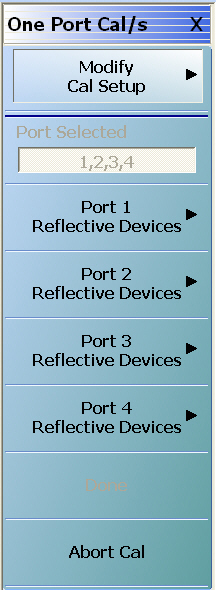
ONE PORT CAL Menu – 4-Port VNAs – Typical example (1 of 2)
Modify Cal Setup
Select displays the CAL SETUP menu where the Edit Cal Params button provides access to the FULL ONE PORT CAL SETUP dialog box for the selected calibration method and line type.
Read-only display of the ports selected for the pending calibration.
Completion Menu Buttons
For this example menu, the Port 1 Reflective Devices to the Isolation (Optional) buttons link to completion submenus where additional calibration procedures are performed.
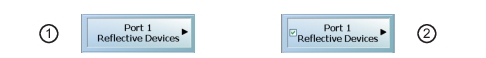
For example, the Port 1 Reflective Devices button (shown below at #1) links to the REFL. DEVICES PORT 1 submenu. As each procedure is completed, the submenu button is marked with a completion checkmark. When all the procedures on the submenu are completed, use the Back button to return to the TWO PORT CAL menu.
The Port 1 Reflective Devices button (shown above at #2) is now marked with a completion checkmark.
Port 1 Reflective Devices
Select displays the REFL. DEVICES PORT 1 submenu. When all procedures are complete, select the Back button to return to the ONE PORT CAL menu where this button is now marked with a completion checkmark.
Select displays the REFL. DEVICES PORT 2 submenu. When all procedures are complete, select the Back button to return to the ONE PORT CAL menu where this button is now marked with a completion checkmark.
Port 3 Reflective Devices
Select displays the REFL. DEVICES PORT 3 submenu. When all procedures are complete, select the Back button to return to the ONE PORT CAL menu where this button is now marked with a completion checkmark.
Port 3 Reflective Devices
Select displays the REFL. DEVICES PORT 3 submenu. When all procedures are complete, select the Back button to return to the ONE PORT CAL menu where this button is now marked with a completion checkmark.
Done
This button is unavailable until a successful calibration procedure has been completed. When available, it returns to the CALIBRATION menu where the Cal Status button is set to ON.
• MAIN | Calibration | CALIBRATION | Calibrate | CALIBRATE | Manual Cal | MANUAL CAL | 1-Port Cal | ONE PORT CAL | Modify Cal Setup | CAL SETUP | Edit Cal Params | ONE PORT CAL SETUP (SOLT/R, Coaxial Dialog Box
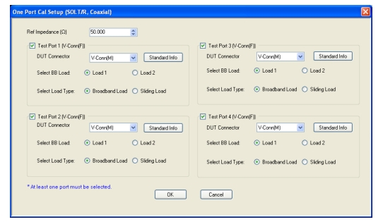
ONE PORT CAL SETUP (SOLT/R, Coaxial) Dialog Box
Reference Impedance
Input the reference impedance.
• Input field defaulted to 50 Ohms.
• Any numerical value accepted, although input values < 0.01 Ohms are converted to 0.01 Ohms.
Test Port Selection Boxes
Allows selection of any combination of Test Port 1, Test Port 2, Test Port 3, or Test Port 4 as long as one port is selected.
If a port is not selected, its buttons and controls are not available.
Test Port 1 DUT Connector
Select the DUT Connector Type from a drop-down menu list with options of:
• 0.8 mm-Conn (M)
• 0.8 mm-Conn (F)
• W1-Conn (M)
• W1-Conn (F)
• V-Conn (M)
• V-Conn (F)
• K-Conn (M)
• K-Conn (F)
• 2.4 mm (M)
• 2.4 mm (F)
• GPC-3.5 (M)
• GPC-3.5 (F)
• SMA (M)
• SMA (F)
• N-Conn (M)
• N-Conn (F)
• N-Conn (75) (M)
• N-Conn (75) (F)
• GPC-7
• 7/16 (M)
• 7/16 (F)
• TNC (M) (Kit from Maury Microwave)
• TNC (F) (Kit from Maury Microwave)
• User-Defined1 (M) through User-Defined32 (M)
• User-Defined1 (F) through User-Defined32 (F)
Test Port 1 Connector Standard Info Button
Select displays the STANDARD INFO dialog box with connector calibration coefficients for the selected connector and calibration method. The dialog box contents depend on the selected connector, calibration method, and line type. The example in the link below shows a typical standard information dialog box.
• If sliding load is selected, a message appears: “Still required broadband loads below sliding load breakpoint frequency.”
Test Port 2, Test Port 3, and Test Port 4 DUT Connector
Select the DUT Connector Type from a drop-down menu list as shown above in Test Port 1.
Test Port 2, Test Port 3, and Test Port 4 Connector Standard Info Button
Select displays the STANDARD INFO dialog box with connector calibration coefficients for the selected connector and calibration method as described above in Test Port 1.
Test Port 2, Test Port 3, and Test Port 4 Load Type
Select the load as either Broadband Load or Sidling Load as describe above in Test Port 1.
OK / Cancel
Click OK to accept the changes and return to the CAL SETUP menu.
Click Cancel to abandon any changes and return to the CAL SETUP menu.
• MAIN | Calibration | CALIBRATION | Calibrate | CALIBRATE | Manual Cal | MANUAL CAL | 1-Port Cal | ONE PORT CAL | Modify Cal Setup | CAL SETUP | Edit Cal Params | ONE PORT CAL SETUP (SSLT, Coaxial Dialog Box
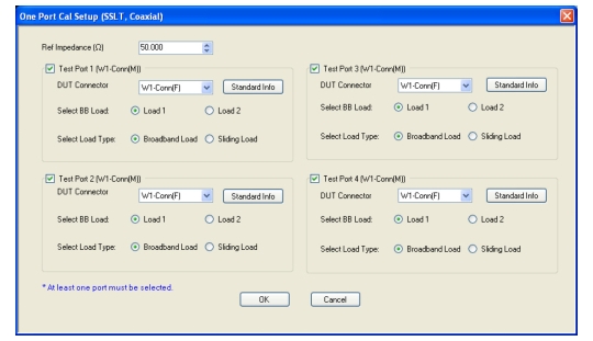
ONE PORT CAL SETUP (SSLT, Coaxial) Dialog Box
Reference Impedance
Input the reference impedance.
• Input field defaulted to 50 Ohms.
• Any numerical value accepted, although input values < 0.01 Ohms are converted to 0.01 Ohms.
Test Port Selection Boxes
Allows selection of any combination of Test Port 1, Test Port 2, Test Port 3, or Test Port 4 as long as one port is selected.
If a port is not selected, its buttons and controls are not available.
Test Port 1 DUT Connector
Select the DUT Connector Type from a drop-down menu list with options of:
• 0.8 mm-Conn (M)
• 0.8 mm-Conn (F)
• W1-Conn (M)
• W1-Conn (F)
• User-Defined1 (M) through User-Defined32 (M)
• User-Defined1 (F) through User-Defined32 (F)
Test Port 1 Connector Standard Info Button
Select displays the STANDARD INFO dialog box with connector calibration coefficients for the selected connector and calibration method. The dialog box contents depend on the selected connector, calibration method, and line type. The examples in the link below shows a typical standard information dialog box.
• If sliding load is selected, a message appears: “Still required broadband loads below sliding load breakpoint frequency.”
Test Port 2, Test Port 3, and Test Port 4 DUT Connector
Select the DUT Connector Type from a drop-down menu list as shown above in Test Port 1.
Test Port 2, Test Port 3, and Test Port 4 Connector Standard Info Button
Select displays the STANDARD INFO dialog box with connector calibration coefficients for the selected connector and calibration method as described above in Test Port 1.
Test Port 2, Test Port 3, and Test Port 4 BB Load
Select the broadband load as either Load 1 or Load 2 as describe above in Test Port 1.
Test Port 2, Test Port 3, and Test Port 4 Load Type
Select the load as either Broadband Load or Sidling Load as describe above in Test Port 1.
OK / Cancel
Click OK to accept the changes and return to the CAL SETUP menu.
Click Cancel to abandon any changes and return to the CAL SETUP menu.
• MAIN | Calibration | CALIBRATION | Calibrate | CALIBRATE | Manual Cal | MANUAL CAL | 1-Port Cal | ONE PORT CAL | Modify Cal Setup | CAL SETUP | Edit Cal Params | ONE PORT CAL SETUP (SSST, Coaxial Dialog Box
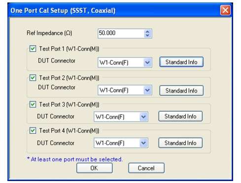
ONE PORT CAL SETUP (SSST, Coaxial) Dialog Box
Reference Impedance
Input the reference impedance.
• Input field defaulted to 50 Ohms.
• Any numerical value accepted, although input values < 0.01 Ohms are converted to 0.01 Ohms.
Test Port Selection Boxes
Allows selection of any combination of Test Port 1, Test Port 2, Test Port 3, or Test Port 4 as long as one port is selected.
If a port is not selected, its buttons and controls are not available.
Test Port 1 DUT Connector
Select the DUT Connector Type from a drop-down menu list with options of:
• 0.8 mm-Conn (M)
• 0.8 mm-Conn (F)
• W1-Conn (M)
• W1-Conn (F)
• User-Defined1 (M) through User-Defined32 (M)
• User-Defined1 (F) through User-Defined32 (F)
Test Port 1 Connector Standard Info Button
Select displays the STANDARD INFO dialog box with connector calibration coefficients for the selected connector and calibration method. The dialog box contents depend on the selected connector, calibration method, and line type. The examples in the link below shows a typical standard information dialog box.
• MAIN | Calibration | CALIBRATION | Calibrate | CALIBRATE | Manual Cal | MANUAL CAL | 1-Port Cal | ONE PORT CAL | Modify Cal Setup | CAL SETUP | Edit Cal Params | ONE PORT CAL (SSLT, Waveguide) Dialog Box
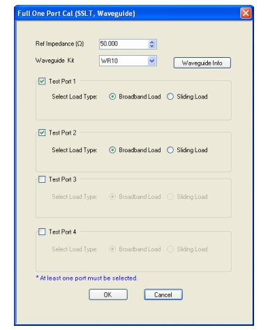
ONE PORT CAL SETUP (SSLT, Waveguide) Dialog Box
Reference Impedance
Input the reference impedance.
• Input field defaulted to 50 Ohms.
• Any numerical value accepted, although input values < 0.01 Ohms are converted to 0.01 Ohms.
Waveguide Kit Selection
Select the Waveguide Kit Type from a drop-down menu list with options of:
• User-Defined 1 through User-Defined 32
Waveguide Info Button
Select displays the USER DEFINED WAVEGUIDE (SSST) parameters dialog box. The dialog box allows user input of waveguide calibration parameters of:
• Waveguide kit label. A user-defined kit label can be input here.
• Cutoff frequency (GHz)
• Dielectric
• Offset short 1 length (mm)
• Offset short 2 length (mm)
• Offset short 3 length (mm)
• A calculator icon provides access to the AIR EQUIVALENT LENGTH CALCULATOR dialog box described in the AutoCal sections above.
The dialog box contents depend on the selected connector, calibration method, and line type. The example in the link below shows a typical standard information dialog box.
• Cal Method = Broadband Cal (SOLT/R-SSST/R) – Appears only with VNA in Broadband Mode (3739)
• Line Type = Coaxial
Navigation
• MAIN | Calibration | CALIBRATION | Calibrate | CALIBRATE | Manual Cal | MANUAL CAL | 1-Port Cal | ONE PORT CAL | Modify Cal Setup | CAL SETUP | Cal Method = Broadband Cal (SOLT/R-SSST/R) | Line Type = Coaxial | Edit Cal Params | ONE PORT CAL SETUP BROADBAND CAL, MERGED SOLT-SSST/SOLR-SSSR) Dialog Box
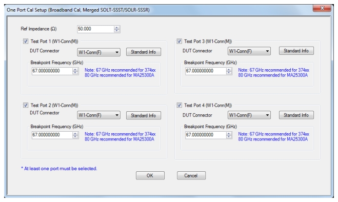
ONE PORT CAL SETUP Broadband Cal, Merged (SOLT/SOLR-SSST/SSSR) Dialog Box
Reference Impedance
• Input field is defaulted to 50 Ohms.
• Any numerical value accepted, although input values < 0.01 Ohms are converted to 0.01 Ohms.
Test Ports Area
Test Port 1 DUT Connector
• Select the DUT Connector type from a drop-down menu list with options of:
• 0.8 mm-Conn (M)
• 0.8 mm-Conn (F)
• W1-Conn (M)
• W1-Conn (F)
• User-Defined1 (M) through User-Defined32 (M)
• User-Defined1 (F) through User-Defined32 (F)
Test Port 1 Connector Standard Info Button
• Select displays the STANDARD INFO dialog box for the selected connector and calibration method that displays the connector calibration coefficients. The dialog box contents depend on the selected connector, Cal Method, and Line Type. The following link shows a typical standard information dialog box for broadband cal.
• 67 GHz is recommended for the 3656 (1 mm) calibration kit.
• 80 GHz is recommended for the 3659 (0.8 mm) calibration kit.
• In this combined calibration, the breakpoint frequency defines the frequency above which the SSS algorithm will be used (and SOL will be used for the frequencies at or below the breakpoint). Default values are based on Anritsu calibration kits and are optimal for those components.
Test Port 2, Test Port 3, and Test Port 4 DUT Connector
• Identical function as with the Test Port 1 DUT Connector Area above. DUT Connector Type is selected from a drop-down menu list.
Test Port 2, Test Port 3, and Test Port 4 Connector Standard Info Button
• Identical function as with the Test Port 1 DUT Connector Standard Info button above. Select displays the STANDARD INFO dialog box for the selected DUT Connector.
Test Port 2, Test Port 3, and Test Port 4 Breakpoint Frequency
• Identical function as with the Test Port 1 Breakpoint Frequency above.
OK / Cancel:
• Click OK to accept the changes or Cancel to abandon any changes and return to the CAL SETUP menu.
• MAIN | Calibration | CALIBRATION | Calibrate | CALIBRATE | Manual Cal | MANUAL CAL | 1-Port Cal | ONE PORT CAL | Modify Cal Setup | CAL SETUP | Edit Cal Params | ONE PORT CAL SETUP (mSSS, Coaxial)
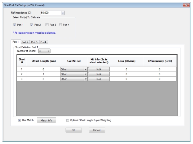
ONE PORT CAL SETUP (mSSS, Coaxial) Dialog Box
Reference Impedance
Input the reference impedance.
• Input field defaulted to 50 Ohms.
• Any numerical value accepted, although input values < 0.01 Ohms are converted to 0.01 Ohms.
Test Ports to Calibrate
Select any test port(s) from Port 1, Port 2, Port 3, and Port 4. At least one test port must be selected.
Test Ports: Port 1 Tab – Short Definition
Number of Shorts
Select number of shorts from 3-10.
Offset Length (mm)
Editable if the Cal Kit Sel selected is “Other”; otherwise it will reflect the offset length of the selected short in the cal kit standard (Kit Info column).
Cal Kit Selection
Select the DUT Connector Type from a drop-down menu list with options of:
• Other
• 0.8 mm-Conn (M)
• 0.8 mm-Conn (F)
• W1-Conn (M)
• W1-Conn (F)
• User-Defined1 (M) through User-Defined32 (M)
• User-Defined1 (F) through User-Defined32 (F)
Kit Info Button
Select displays the STANDARD INFO or USER DEFINED STANDARD dialog box for the selected connector and calibration method that displays the connector calibration coefficients. The dialog box contents depend on the selected connector, Cal Method, and Line Type. The examples show typical standard information dialog boxes.
• Since the STANDARD INFORMATION (mSSS) dialog derives from the SSS calibration kit definition, three shorts are available and the one to be used for the current line in the mSSS table is defined by the Select Short to use field. All of the shorts in the kit can be employed in the mSSS calibration, but each must be assigned to a separate line in the table.
This field (in conjunction with the @Frequency field and the offset length) is used to compute the loss in the short and hence the magnitude of its reflection coefficient. This is mainly relevant for very large offset lengths (> 10 mm) at microwave frequencies or somewhat shorter lengths at millimeter wave frequencies.
@Frequency (GHz)
This field (in conjunction with the loss in dB/mm and the offset length) is used to compute the loss of the offset short (and hence the magnitude of its reflection coefficient) at each frequency. If a non-zero value is entered here, it is treated as the reference frequency fref at which the loss (dB/mm) was defined and the loss at all other frequencies is scaled by sqrt(f/fref). If 0 is entered here, the loss is assumed to be constant with frequency.
Use Match Checkbox
When this box is checked, a match measurement is acquired during the calibration and is used whenever even the collection of offset shorts does not have enough phase separation (value defined within the USER DEFINED MATCH dialog: Electrical line length delta for match use, expressed in degrees). The decision to use the match data is made on a frequency-by-frequency basis. See the MS464XB Calibration and Measurement Guide for more information. This helps increase bandwidth of the calibration, particularly at lower frequencies, if a match standard is available.
When this box is checked, more weight is given to those offset shorts that contribute most to large electrical length deltas and hence to bandwidth of the calibration. More details can be found in the MS464XB Calibration and Measurement Guide. Using this feature can increase the available bandwidth of the calibration, but does reduce immunity to repeatability variances in the setup, so it is not advised in more repeatability challenged scenarios (e.g., fixtures where the short standards are attached by spring force alone).
Port 2, Port 3, and Port 4 Tabs – Short Definition
Identical functions as with the Test Ports: Port 1 Tab above.
OK / Cancel
Click OK to accept the changes and return to the CAL SETUP menu.
Click Cancel to abandon any changes and return to the CAL SETUP menu.
Summary of 1-Port Calibration Setup Dialog Boxes
The table below summarizes the fields and controls in all 1-port calibration setup dialog boxes. If the dialog box is described in greater detail above, a link is provided to that description. To view each dialog box, set the CAL METHOD and LINE TYPE menus to the appropriate settings, and then select the Edit Cal Params button. All three-port dialog boxes are named “Three Port Cal Setup (Cal Method, Line Type)”
1-Port Manual Cal Setup Dialog Box Summary – 4-Port VNAs (1 of 6)
Select Test Ports: Select any combination of Test Port 1, Test Port 2, Test Port 3, and/or Test Port 4 as long as one port is selected.
Test Port DUT Connector: For each test port, select one of the following connectors from a drop-down list: 0.8 mm-Conn (M), 0.8 mm-Conn (F)W1-Conn (M), W1-Conn (F), V-Conn (M), V-Conn (F), K-Conn (M), K-Conn (F), 2.4 mm (M), 2.4 mm (F), 2.4 mm V (M), 2.4 mm V (F), GPC-3.5 (M), GPC-3.5 (F), SMA (M), SMA (F), N-Conn (M), N-Conn (F), N-Conn (75) (M), N-Conn (75) (F), GPC-7, 7/16 (M), 7/16 (F), TNC (M), TNC (F), User-Defined1 (M) through User-Defined32 (M), User-Defined1 (F) through User-Defined32 (F)
Test Port DUT Connector Standard Info Button: Select displays the STANDARD INFO dialog box for the selected connector above.
Select Test Ports: Select any combination of Test Port 1, Test Port 2, Test Port 3, and/or Test Port 4 as long as one port is selected.
Test Port DUT Connector: For each test port, select one of the following connectors from a drop-down list: 0.8 mm-Conn (M), 0.8 mm-Conn (F) W1-Conn (M), W1-Conn (F), V-Conn (M), V-Conn (F), K-Conn (M), K-Conn (F), 2.4 mm (M), 2.4 mm (F), 2.4 mm V (M), 2.4 mm V (F), GPC-3.5 (M), GPC-3.5 (F), SMA (M), SMA (F), N-Conn (M), N-Conn (F), N-Conn (75) (M), N-Conn (75) (F), GPC-7, 7/16 (M), 7/16 (F), TNC (M), TNC (F), User-Defined1 (M) through User-Defined32 (M), User-Defined1 (F) through User-Defined32 (F)
Test Port DUT Connector Standard Info Button: Select displays the STANDARD INFO dialog box for the selected connector above.
Test Port Connector Standard Info Button: For each port selected, displays the USER DEFINED STANDARD dialog box for the selected calibration method and connector. See the following links for typical examples:
Select the DUT Connector Type from a drop-down menu list with options of:
0.8 mm-Conn (M), 0.8 mm-Conn (F), W1-Conn (M), W1-Conn (F), User-Defined1 (M) through User-Defined32 (M), User-Defined1 (F) through User-Defined32 (F)
Test Port 1 Connector Standard Info Button
Select displays the STANDARD INFO dialog box for the selected connector and calibration method that displays the connector calibration coefficients. The dialog box contents depend on the selected connector, Cal Method, and Line Type. The following link shows a typical standard information dialog box for broadband cal.
67 GHz is recommended for the 3656 (1 mm) calibration kit. 80 GHz is recommended for the 3659 (0.8 mm) calibration kit.
Test Port 2, Test Port 3, and Test Port 4 Connector Type Area:
Identical function as with the Test Port 1 Connector Area above. Select the DUT Connector Type from a drop-down menu list.
Test Port 2, Test Port 3, and Test Port 4 Connector Standard Info Button:
Identical function as with the Test Port 1 Connector Standard Info Button above. Select displays the STANDARD INFO dialog box for the selected DUT Connector.
Test Port 2, Test Port 3, and Test Port 4 Breakpoint Frequency
Identical function as with the Test Port 1 Breakpoint Frequency area above.
OK / Cancel:
Click OK to accept the changes or Cancel to abandon any changes and return to the CAL SETUP menu.
TRL/TRM
The TRL/TRM calibration method is not available for 1-port calibrations.
LRL/LRM
The LRL/LRM calibration method is not available for 1-port calibrations.
mTRL
The mTRL calibration method is not available for 1-port calibrations.
Loss (dB/mm): Used to compute the loss in the short and hence the magnitude of its reflection coefficient.
@Frequency: Used to compute the loss of the offset short (and hence the magnitude of its reflection coefficient) at each frequency.
Use Match: When this box is checked, a match measurement is acquired during the calibration and is used whenever even the collection of offset shorts does not have enough phase separation.
Optimal Offset Length Super-Weighting: When this box is checked, more weight is given to those offset shorts that contribute most to large electrical length deltas and hence to bandwidth of the calibration.
Test Port 1, Test Port 2, Test Port 3, and Test Port 4 controls are the same.
mSSS
Non-Dispersive
Same controls as mSSS Coaxial above.
mSSS
Waveguide
Same controls as mSSS Coaxial with the following changes:
Cal Kit Selection: User-Defined1 through User-Defined32.
Cutoff Frequency: The cutoff frequency for the TE10 mode in the waveguide size being used for this calibration (all shorts are assumed to have the same aperture dimensions and hence the same cutoff frequency).
Dielectric: The dielectric constant of any filling material in the waveguide interface being used for the calibration (assumed 100% fill; default value is 1).
mSSS
Microstrip
Same controls as mSSS Coaxial with the following changes:
Cal Kit Selection: User-Defined1 through User-Defined32.
Microstrip Kit: 10 Mil Kit, 15 Mil Kit, 25 Mil Kit, User-Defined 1 to User-Defined 32
Microstrip Info button: Displays MICROSTRIP INFO dialog box for selected calibration method and kit.