Manual Trans. Freq. Resp. Cal Menus and Dialog Boxes
Full Name
Transmission Frequency Response Calibration
Menu Name
Trans. Response
Button Name
Transmission Freq. Response
TRANS. RESPONSE Menu – 4-Port VNAs
The exact composition of the menu depends on the settings made on the CAL SETUP, CAL METHOD, and LINE TYPE menus and on the resultant TRANSMISSION FREQUENCY REPONSE CAL SETUP dialog box. A representative menu is shown below. There is one example procedure of a TRANS. RESPONSE calibration in this chapter.
• MAIN | Calibration | CALIBRATION | Calibrate | CALIBRATE | Manual Cal | MANUAL CAL | Transmission Freq. Response | TRANS. RESPONSE
TRANS. RESPONSE Menu – 4-Port VNAs – Typical example (1 of 2)
Modify Cal Setup
Select displays the CAL SETUP menu where the Edit Cal Params button provides access to the TRANSMISSION FREQUENCY RESPONSE CAL SETUP dialog box for the selected calibration method and line type.
Read-only display of the ports selected for the pending calibration.
Other Menu Buttons
For this example menu, the buttons below Port Selected to the Isolation (Optional) button each display calibration completion submenus. Once the calibration steps on each submenu are complete, these menu buttons are marked as completed.
Done
This button is unavailable until a successful calibration procedure has been completed. When available, it returns to the CALIBRATION menu where the Cal Status button is set to ON.
• MAIN | Calibration | CALIBRATION | Calibrate | CALIBRATE | Manual Cal | MANUAL CAL | Transmission Freq. Response | TRANS. RESPONSE | Modify Cal Setup | CAL SETUP | Edit Cal Params | TRANSMISSION FREQUENCY RESPONSE CAL SETUP (SOLT/R, Coaxial) Dialog Box
• CAL SETUP must be set to Cal Method = SOLT/SOLR and Line Type = Coaxial.
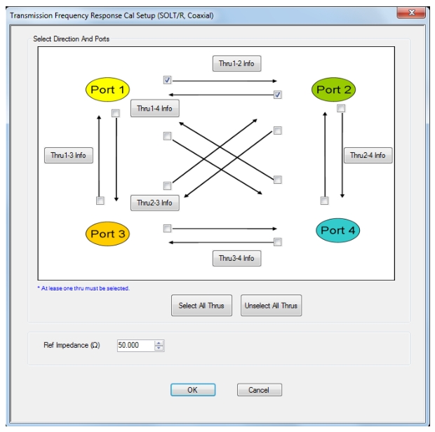
TRANS. FREQ. RESP. CAL SETUP (SOLT/R, Coaxial) Dialog Box
Test Port Thru Selection Boxes
Allows selection of any combination of the test port throughs for the available port pairs:
• Thru 1-2
• Thru 1-3
• Thru 1-4
• Thru 2-3
• Thru 2-4
• Thru 3-4
Test Port Pair Thru Info Buttons
A Thru Info button becomes available for each port pair through selected above. Select displays the THRU INFO configuration dialog box for the selected port pair. A calculator icon in the THRU INFO dialog box allows access to the AIR EQUIVALENT LENGTH CALCULATOR dialog box.
• MAIN | Calibration | CALIBRATION | Calibrate | CALIBRATE | Manual Cal | MANUAL CAL | Transmission Freq. Response | TRANS. RESPONSE | Modify Cal Setup | CAL SETUP | Edit Cal Params | TRANSMISSION FREQUENCY RESPONSE CAL SETUP (SOLT/R, Coaxial) Dialog Box
• CAL SETUP must be set to Cal Method = SSLT and Line Type = Waveguide.
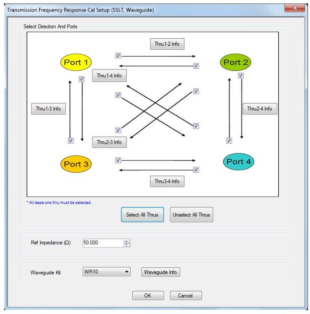
TRANS. FREQ. RESP. CAL SETUP (SSLT, Waveguide) Dialog Box
TRANSMISSION FREQUENCY RESPONSE CALIBRATION SETUP
Test Port Pair Thru Info Buttons
A Thru Info button becomes available for each port pair through selected above. Select displays the THRU INFO configuration dialog box for the selected port pair. A calculator icon in the THRU INFO dialog box allows access to the AIR EQUIVALENT LENGTH CALCULATOR dialog box.
The dialog box contents depend on the selected connector, calibration method, and line type. The example in the link below shows a typical standard information dialog box.
• MAIN | Calibration | CALIBRATION | Calibrate | CALIBRATE | Manual Cal | MANUAL CAL | Transmission Freq. Response | TRANS. RESPONSE | Modify Cal Setup | CAL SETUP | Edit Cal Params | TRANSMISSION FREQUENCY RESPONSE CAL SETUP (SSST, Coaxial) Dialog Box
• CAL SETUP must be set to Cal Method = SSST and Line Type = Microstrip.
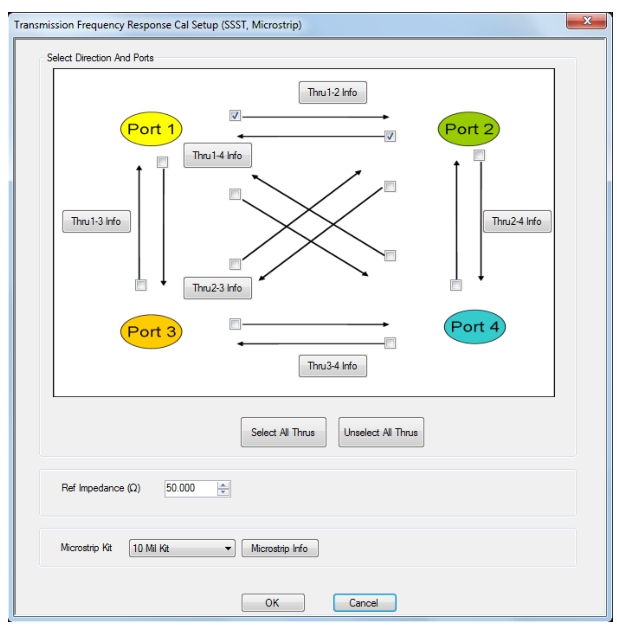
TRANS. FREQ. RESP. CAL SETUP (SSST, Microstrip) Dialog Box
Test Port Pair Thru Info Buttons
A Thru Info button becomes available for each port pair through selected above. Select displays the THRU INFO configuration dialog box for the selected port pair. A calculator icon in the THRU INFO dialog box allows access to the AIR EQUIVALENT LENGTH CALCULATOR dialog box.
• Any numerical value accepted, although input values < 0.01 Ohms are converted to 0.01 Ohms.
Test Port Selection Boxes
Allows selection of any combination of Test Port 1, Test Port 2, Test Port 3, or Test Port 4 as long as one port is selected.
If a port is not selected, its buttons and controls are not available.
Test Port 1 Select Cal Component
Select from Offset Short 1, Offset Short 2, or Offset Short 3
Test Port 1 DUT Connector
Select the DUT Connector Type from a drop-down menu list with options of:
• User-Defined1 through User-Defined32
Test Port 1 Connector Standard Info Button
Select displays the USER DEFINED OFFSET SHORT INFO dialog box with connector calibration coefficients for the selected connector and calibration method. The dialog box contents depend on the selected connector, calibration method, and line type. See the following links for typical examples:
Test Port 2, Test Port 3, and Test Port 4 DUT Connector
Select the DUT Connector Type from a drop-down menu list as shown above in Test Port 1.
Test Port 2, Test Port 3, and Test Port 4 Connector Standard Info Button
Select displays the USER DEFINED SHORT INFO dialog box with connector calibration coefficients for the selected connector and calibration method as described above in Test Port 1.
OK / Cancel
Click OK to accept the changes and return to the CAL SETUP menu.
Click Cancel to abandon any changes and return to the CAL SETUP menu.
Summary of Trans. Freq. Resp. Cal Setup Dialog Boxes
The table below summarizes the fields and controls in all transmission frequency response calibration setup dialog boxes. If the dialog box is described in greater detail above, a link is provided to that description. To view each dialog box, set the CAL METHOD and LINE TYPE menus to the appropriate settings, and then select the Edit Cal Params button. All transmission frequency response dialog boxes are named “Transmission Frequency Response Cal Setup (Cal Method, Line Type)”
Trans. Freq. Resp. Manual Cal Setup Dialog Box Summary – 4-Port VNAs (1 of 2)
Select Test Port Throughs: Select any combination of port pair throughs from Thru 1-2, Thru 1-3, Thru 1-4, Thru 2-3, Thru 2-4, and/or Thru 1-3. At least one through must be selected.
Thru Info Button: For each through selected above, the Thru Info [Port Pair] button is enabled. Select the Thru Info button to display the THRU INFO dialog box.
Same controls and functions as SOLT/R Coaxial above.
SOLT/R
Waveguide
Same controls and functions as SOLT/R Coaxial with the following changes:
Waveguide Kit: Select from User-Defined 1 to User-Defined 32
Waveguide Info button: Displays the USER DEFINED WAVEGUIDE dialog box for the waveguide kit selected above. Define the waveguide by entering values for: Cutoff frequency (GHz), Dielectric constant
Same controls and functions as SOLT/R Coaxial with the following changes:
Waveguide Kit: Select from Wr10, WR15, WR20, and User-Defined 1 to User-Defined 32
Waveguide Info button: Select displays either the WAVEGUIDE INFO (SSLT) or the USER DEFINED WAVEGUIDE dialog box for the waveguide kit selected above. Define the user waveguide by entering values for: Cutoff frequency (GHz), Dielectric constant