The exact composition of the menu depends on the settings made on the CAL SETUP, CAL METHOD, and LINE TYPE menus and on the resultant TRANSMISSION FREQUENCY REPONSE CAL SETUP dialog box. A representative menu is shown below. The example procedures in this chapter show one example of a TRANS. RESPONSE menu.
• MAIN | Calibration | CALIBRATION | Calibrate | CALIBRATE | Manual Cal | MANUAL CAL | Reflection Freq. Response | REFL. RESPONSE
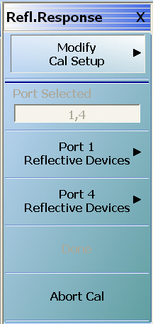
REFL. RESPONSE Menu – 4-Port VNAs – Typical example (1 of 2)
Modify Cal Setup
Select displays the CAL SETUP menu where the Edit Cal Params button provides access to the REFLECTION FREQ. RESPONSE CAL SETUP dialog box for the selected calibration method and line type.
Read-only display of the ports selected for the pending calibration.
Other Menu Buttons
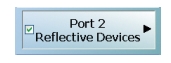
For this example menu, the buttons below Port Selected to the Isolation (Optional) button each display calibration completion submenus. Once the calibration steps on each submenu are complete, these menu buttons are marked as completed.
Done
This button is unavailable until a successful calibration procedure has been completed. When available, it returns to the CALIBRATION menu where the Cal Status button is set to ON.
• MAIN | Calibration | CALIBRATION | Calibrate | CALIBRATE | Manual Cal | MANUAL CAL | Reflection Freq. Response | REFL. RESPONSE | Modify Cal Setup | CAL SETUP | Edit Cal Params | REFLECTION FREQ. RESPONSE CAL SETUP (SOLT/R, Coaxial) Dialog Box
• CAL SETUP must be set to Cal Method = SOLT/R and Line Type = Coaxial.
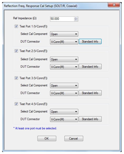
REFL. FREQ. RESP. CAL SETUP (SOLT/R, Coaxial) Dialog Box
REFLECTION FREQUENCY RESPONSE CALIBRATION SETUP
Reference Impedance
Input the reference impedance.
• Input field defaulted to 50 Ohms.
• Any numerical value accepted, although input values < 0.01 Ohms are converted to 0.01 Ohms.
Test Port Selection Boxes
Allows selection of any combination of Test Port 1, Test Port 2, Test Port 3, or Test Port 4 as long as one port is selected.
If a port is not selected, its buttons and controls are not available.
Test Port 1 Select Cal Component
Select from Open or Short
Test Port 1 DUT Connector
Select the DUT Connector Type from a drop-down menu list with options of:
• 0.8 mm-Conn (M)
• 0.8 mm-Conn (F)
• W1-Conn (M)
• W1-Conn (F)
• V-Conn (M)
• V-Conn (F)
• K-Conn (M)
• K-Conn (F)
• 2.4 mm (M)
• 2.4 mm (F)
• GPC-3.5 (M)
• GPC-3.5 (F)
• SMA (M)
• SMA (F)
• N-Conn (M)
• N-Conn (F)
• N-Conn (75) (M)
• N-Conn (75) (F)
• GPC-7
• 7/16 (M)
• 7/16 (F)
• TNC (M) (Kit from Maury Microwave)
• TNC (F) (Kit from Maury Microwave)
• User-Defined1 (M) through User-Defined32 (M)
• User-Defined1 (F) through User-Defined32 (F)
Test Port 1 Connector Standard Info Button
Select displays the STANDARD INFO dialog box with connector calibration coefficients for the selected connector and calibration method. The dialog box contents depend on the selected connector, calibration method, and line type. See the following links for typical examples:
Test Port 2, Test Port 3, and Test Port 4 DUT Connector
Select the DUT Connector Type from a drop-down menu list as shown above in Test Port 1.
Test Port 2, Test Port 3, and Test Port 4 Connector Standard Info Button
Select displays the STANDARD INFO dialog box with connector calibration coefficients for the selected connector and calibration method as described above in Test Port 1.
OK / Cancel
• Click OK to accept the changes and return to the CAL SETUP menu.
• Click Cancel to abandon any changes and return to the CAL SETUP menu.
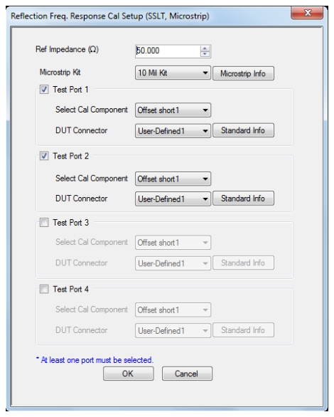
REFL. FREQ. RESP. CAL SETUP (SSLT, Microstrip) Dialog Box
Full Name
Reflection Frequency Response Calibration Setup (SSLT, Microstrip)
• MAIN | Calibration | CALIBRATION | Calibrate | CALIBRATE | Manual Cal | MANUAL CAL | Reflection Freq. Response | REFL. RESPONSE | Modify Cal Setup | CAL SETUP | Edit Cal Params | REFLECTION FREQ. RESPONSE CAL SETUP (SSLT, Microstrip) Dialog Box
• CAL SETUP must be set to Cal Method = SSLT and Line Type = Microstrip.
REFL. FREQ. RESP. CAL SETUP (SSLT, Microstrip) Dialog Box
REFLECTION FREQUENCY RESPONSE CALIBRATION SETUP
Reference Impedance
Input the reference impedance.
• Input field defaulted to 50 Ohms.
• Any numerical value accepted, although input values < 0.01 Ohms are converted to 0.01 Ohms.
Test Port Selection Boxes
Allows selection of any combination of Test Port 1, Test Port 2, Test Port 3, or Test Port 4 as long as one port is selected.
If a port is not selected, its buttons and controls are not available.
Test Port 1 Select Cal Component
Select from Offset Short 1 or Offset Short 2
Test Port 1 DUT Connector
Select the DUT Connector Type from a drop-down menu list with options of:
• User-Defined1 through User-Defined32
Test Port 1 Connector Standard Info Button
Select displays the USER DEFINED SHORT INFO dialog box with connector calibration coefficients for the selected connector and calibration method. The dialog box contents depend on the selected connector, calibration method, and line type. See the following links for typical examples:
Test Port 2, Test Port 3, and Test Port 4 DUT Connector
Select the DUT Connector Type from a drop-down menu list as shown above in Test Port 1.
Test Port 2, Test Port 3, and Test Port 4 Connector Standard Info Button
Select displays the USER DEFINED SHORT INFO dialog box with connector calibration coefficients for the selected connector and calibration method as described above in Test Port 1.
OK / Cancel
Click OK to accept the changes and return to the CAL SETUP menu.
Click Cancel to abandon any changes and return to the CAL SETUP menu.
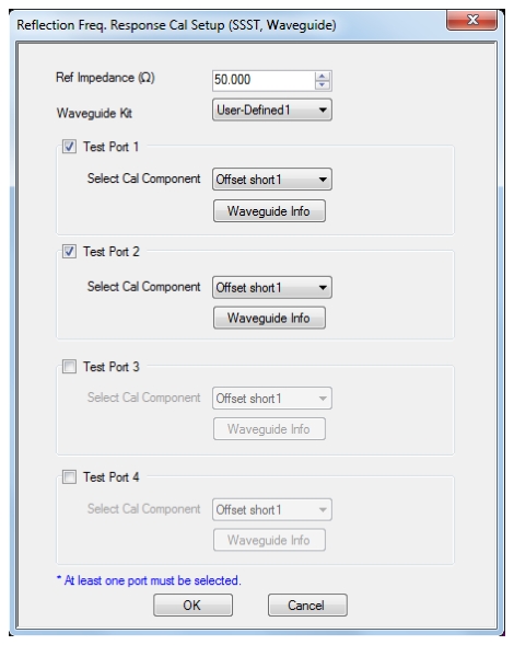
REFL. FREQ. RESP. CAL SETUP (SSST, Waveguide) Dialog Box
Full Name
Reflection Frequency Response Calibration Setup (SSST, Waveguide)
The dialog box contents depend on the selected connector, calibration method, and line type. The example in the link below shows a typical standard information dialog box.
Test Port 2, Test Port 3, and Test Port 4 Controls
The controls for these test ports are the same as those for Test Port 1.
OK / Cancel
Click OK to accept the changes and return to the CAL SETUP menu.
Click Cancel to abandon any changes and return to the CAL SETUP menu.
Summary of Refl. Freq. Resp. Calibration Setup Dialog Boxes
The table below summarizes the fields and controls in all Reflection Frequency Response calibration setup dialog boxes. If the dialog box is described in greater detail above, a link is provided to that description. To view each dialog box, set the CAL METHOD and LINE TYPE menus to the appropriate settings, and then select the Edit Cal Params button. All reflection frequency response dialog boxes are named “Reflection Freq. Response Cal Setup (Cal Method, Line Type)”
Refl. Freq. Resp. Manual Cal Setup Dialog Box Summary – 4-Port VNAs (1 of 3)
Select Test Ports: Select any combination of Test Port 1, Test Port 2, Test Port 3, and/or Test Port 4 as long as one port is selected.
Select Test Port Cal Component: For each selected test port, select Open or Short.
Test Port DUT Connector: For each selected test port, select one of the following connectors from a drop-down list: 0.8 mm-Conn (M), 0.8 mm-Conn (F), W1-Conn (M), W1-Conn (F), V-Conn (M), V-Conn (F), K-Conn (M), K-Conn (F), 2.4 mm (M), 2.4 mm (F), 2.4 mm V (M), 2.4 mm V (F), GPC-3.5 (M), GPC-3.5 (F), SMA (M), SMA (F), N-Conn (M), N-Conn (F), N-Conn (75) (M), N-Conn (75) (F), GPC-7, 7/16 (M), 7/16 (F), TNC (M), TNC (F), User-Defined1 (M) through User-Defined32 (M), User-Defined1 (F) through User-Defined32 (F)
DUT Connector Standard Info Button: Select displays the STANDARD INFO dialog box for the selected connector above.
Same controls and functions as SOLT/R Coaxial with the following changes:
Waveguide Kit: Select User-Defined 1 to User-Defined 32
Waveguide Info button: Depending on the Open/Short component selection above, displays either the USER DEFINED WAVEGUIDE PARAMS or the USER DEFINED WAVEGUIDE SHORT dialog box for the waveguide kit selected above.
Test Port DUT Connector: Select User-Defined 1 to User-Defined 32
Test Port DUT Connector Standard Info Button: Depending on the Cal Component selected above, displays either the USER DEFINED OPEN or the USER DEFINED SHORT dialog box. See the following links for typical examples:
SSLT Coaxial
Same controls and functions as SOLT/R Coaxial with the following changes:
Select Cal Component: Offset short 1 or Offset short 2
Test Port DUT Connector: Select 0.8 mm-Conn (M), 0.8 mm-Conn (F), W1 Conn (F), W1 Conn (M), User-Defined 1 (F) to User-Defined 32 (F), User-Defined 1 (M) to User Defined 32 (M)
Test Port DUT Connector Standard Info Button: Depending on the Cal Component selected above, displays either the STANDARD INFO or the USER DEFINED OFFSET SHORT dialog box. See the following links for typical examples:
Same controls and functions as SOLT/R Coaxial with the following changes:
Waveguide Kit: WR10, WR12, WR15, User-Defined 1 to User-Defined 32
Select Cal Component: Offset short 1 or Offset short 2
Test Port Waveguide Info Button: Depending on the Cal Component selected above, displays either the STANDARD INFO or the USER DEFINED OFFSET SHORT dialog box. See the following links for typical examples:
Test Port Cal Component: Offset short 1 or Offset short 2.
Test Port DUT Connector: User-Defined 1 to User-Defined 32
Test Port Connector Standard Info Button: For each port selected above, displays the USER DEFINED STANDARD dialog box for the selected calibration method and connector. See the following links for typical examples:
SSST
Coaxial
Same controls and functions as SOLT/R Coaxial with the following changes:
Test Port Cal Component: Offset short 1 or Offset short 2.
Test Port DUT Connector: Select 0.8 mm-Conn (M), 0.8 mm-Conn (F), W1 Conn (F), W1 Conn (M), User-Defined 1 (F) to User-Defined 32 (F), User-Defined 1 (M) to User Defined 32 (M)
Test Port Connector Standard Info Button: For each port selected above, displays the STANDARD INFO dialog box for the selected calibration method and connector. See the following links for typical examples:
Same controls and functions as SSST Coaxial above.
SSST Waveguide
Same controls and functions as SSST Coaxial above with the following changes:
Waveguide Kit: User-Defined 1 to User-Defined 32
Test Port Cal Component: Offset short 1, Offset short, Offset short 3.
Waveguide Info button: Displays USER DEFINED WAVEGUIDE INFO dialog box for selected calibration method and kit. See the following links for typical examples:
Test Port DUT Connector: User-Defined 1 to User-Defined 32
Test Port Connector Standard Info Button: For each port, displays the USER DEFINED OFFSET SHORT dialog box for the selected calibration method and connector. See the following links for typical examples:
TRL/TRM
The TRL/TRM calibration method is not available for the Reflection Frequency Response calibrations.
LRL/LRM
The LRL/LRM calibration method is not available for the Reflection Frequency Response calibrations.
mTRL
The mTRL calibration method is not available for Reflection Frequency Response calibrations.
mSSS
The mSSS calibration method is not available for Reflection Frequency Response calibrations.
 p
p