The Gain Compression button availability and access to the underlying GAIN COMPRESS menu depends on the Sweep Type set as described below. In addition, there are two GAIN COMPRESS menu variants described here as the GAIN COMPRESS Self Normalization menu and the GAIN COMPRESS Compress Param menu. The conditions for each is described immediately below.
Types of Gain Compression
The GAIN COMPRESS. (GAIN COMPRESSION) menu provides control of all gain compression parameters. Two menu variants are available depending on the power sweep type selected.
• CW Frequency Gain Compression – The CW Frequency gain compression is a trace function in power sweep CW mode and separate compression points can be set for each trace display. The trace labels are changed with an @CP notation after the measured S-Parameter. Typical trace labels are shown below:
• Without Gain Compression: Tr1 S21 Trans LogM
• With Gain Compression: Tr1 S21@CP Trans LogM
• Swept Frequency Gain Compression – The Swept Frequency gain compression is also a trace function in power sweep swept-frequency mode, and by default, the displays shows the output power verses frequency at the gain compression point. The compression parameter is set to S21 and the plotting parameter set to B2/1 (B2 divided by 1). The trace labels also change with the @CP notation as described above
Gain Compression Button Not Available
If the Gain Compression button on the DISPLAY menu is not available, Sweep Types is set to one of the following:
To make the Gain Compression button on the DISPLAY menu and GAIN COMPRESS menu available, Sweep Types on the SWEEP SETUP menu must be set to Power (CW Freq) or Power (Swept Freq). Each setting enables a different menu variant which are described in the sections below.
GAIN COMPRESS Self Normalization Menu
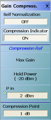
If Sweep Type is set to Power (CW Freq), the GAIN COMPRESS. menu is termed the GAIN COMPRESS. Self Normalization) menu, has six (6) buttons, and the top button is Self Normalization.
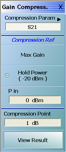
If Sweep Type is set to Power (Swept Freq), the GAIN COMPRESS. menu is termed the GAIN COMPRESS. Compress Param menu, has six (6) buttons, and the top button is Compression Param.
The appearance and button availability of the GAIN COMPRESS menu depends on settings on the SWEEPTYPES menu. Consult the Gain Compression Menus and Dialog Boxes section above for menu identification and prerequisites.
Select toggles the self normalization function OFF and ON. If ON, self normalization normalizes the trace display reference to the first data point of each sweep.
Compression Indicator (Off/On)
Select toggles the screen trace display compression indicators between OFF and ON. If the Compression Indicator is toggled ON, and the instrument finds the compression points, the general display is R and C where:
• The reference point indicator is labeled R
• The gain compression indicator is labeled C with parametric data displayed at the top of the trace window
• The Trace Label is identified with the @CP label after the Measurement Type such as Tr3 S21@CP Trans LogM.
Reference (R) Indicator
If the instrument cannot find the reference points, the R and C labels will not be displayed and will instead display the following messages:
• C:Not Found in the graph display area
• Invalid Reference Value in the display status bar
Compression Reference Point
If the compression reference is set to maximum gain, the instrument will always find the reference point. The instrument may not be able to find the reference point if:
• The compression points are outside the range setting
• The Hold Power setting is outside of the X-axis range on the trace display graph
• The P-in setting is outside of the X-axis range on the trace display graph
Compression (C) Indicator
If the instrument cannot find the compression points, the C label will not be displayed but instead display the message C:Not Found in the graph display area.
DUT or Compression Point Value
The instrument may not be able to find the compression point because of the characteristics of the DUT or because of compression point value.
Compression Reference Button Selection Group
The Max P Out, Hold Power, and P in buttons of the Compression Reference area form a three-button selection group where the selection of one button de-selects the other two (2) buttons.
Max P Out
Select sets the maximum power output available to the instrument.
Hold Power (-XX dBm)
Read-only display. Shows the hold power level on a per-system basis. It defaults to the lowest port source power of -20 dBm. The Hold Power Level is set on the HOLD CONDITIONS menu.
• The appearance and button availability of the GAIN COMPRESS menu depends on settings on the SWEEP TYPES menu. Consult the section above for menu identification and prerequisites.
• MAIN | Display | DISPLAY | Gain Compression | GAIN COMPRESS. Compression Param.
GAIN COMPRESS. Compression Param. Menu (1 of 2)
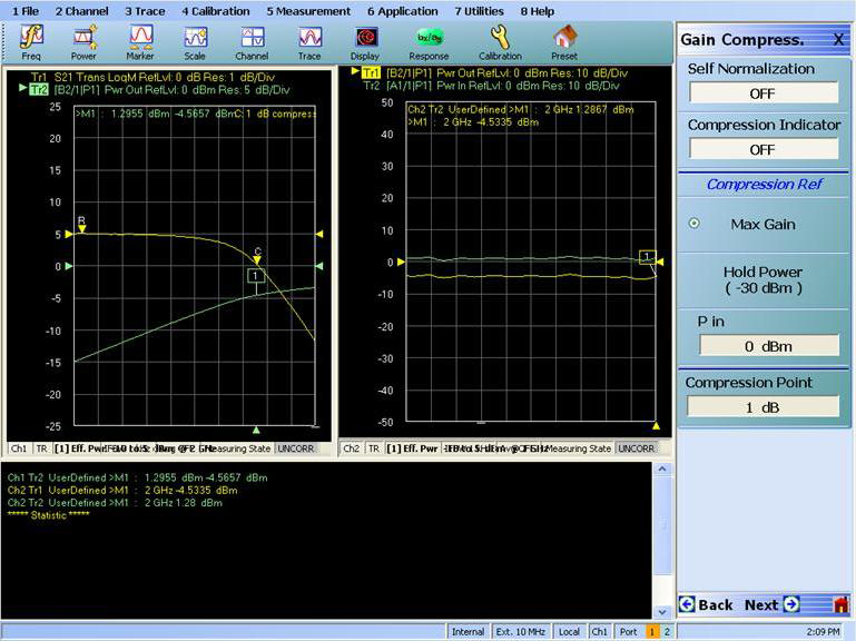
Display Example
For a sample display, see Figure: Gain Compression Display with Power Sweep below. When Gain Compression is on, the Trace Label is identified with the @CP label after the Measurement Type such as Tr3 S21@CP Trans LogM.
Compression Param
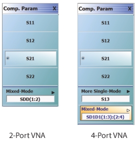
Select displays the COMP PARAM (Compression Parameter) menu which allows the user to select which S-Parameter (S11, S12, S21, S22) is to be used.
The three (3) buttons of the Compression Reference area form a button selection group where the selection of any one button de-selects the other two (2) buttons.
Max Gain
Select sets the maximum gain output available to the instrument.
Hold Power (-XX dBm)
Read-only display. Shows the hold power level on a per-system basis. It defaults to the lowest port source power of -20 dBm. The hold power level is set on the Hold Conditions menu.
• MAIN | Display | DISPLAY | Gain Compression | GAIN COMPRESS. Compression Param | Compression Param | COMP. PARAM
COMP. PARAM (COMPRESSION PARAMETER) Menu
Auto-Return Button Selection Group
The COMP. PARAM menu buttons form an auto-return button selection group where selection of one button de-selects all other buttons and then auto-returns to the GAIN COMPRESS menu.
S11 (Comp Param)
Select sets the compression parameter to S11 – Forward Reflection and auto-returns to the GAIN COMPRESS. menu.
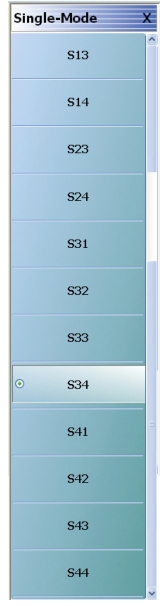
Select opens the SINGLE-MODE menu, which allows setting of additional compression parameters (S13, S23, S32, S33, S14, S24, S34, S41, S42, S43, S44) and auto-returns to the GAIN COMPRESS. menu.
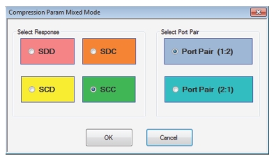
The Compression Parameter Mixed Mode dialog allows selection of mixed mode to be used as the compression parameter.
Define Balanced Port Pair/s Area
Select de-selects all other menu buttons for three general mixed-mode configurations of:
• Two differential pairs
• One differential pair and one singleton
• One differential pair and two singletons
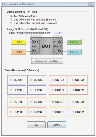
Assign DUT Ports to VNA Ports Area
Toggle the port numbers and click the Apply Port Selection button.
Select Response Area (2 Differential)
Select the appropriate response. Response options will vary according to Balanced Port Pair/s selection.
Select the required 2-differential response characteristic from the available 16 combinations of pure differential (D) and common-mode (C) parameters. Only one compression parameter response may be selected:
• Differential Reception with Differential Drive S-Parameters
• SD1D1 – S-parameter for differential reception at Pair 1 and differential drive at Pair 1.
• SD1D2 – S-parameter for differential reception at Pair 1 and differential drive at Pair 2.
• SD2D1 – S-parameter for differential reception at Pair 2 and differential drive at Pair 1.
• SD2D2 – S-parameter for differential reception at Pair 2 and differential drive at Pair 2.
• Common-Mode Reception with Differential Drive S-Parameters
• SC1D1 – S-parameter for common-mode reception at Pair 1 and differential drive at Pair 1.
• SC1D2 – S-parameter for common-mode reception at Pair 1 and differential drive at Pair 2.
• SC2D1 – S-parameter for common-mode reception at Pair 2 and differential drive at Pair 1.
• SC2D2 – S-parameter for common-mode reception at Pair 2 and differential drive at Pair 2.
• Differential Reception with Common-Mode Drive S-Parameters
• SD1C1 – S-parameter for differential reception at Pair 1 and common-mode drive at Pair 1.
• SD1C2 – S-parameter for differential reception at Pair 1 and common-mode drive at Pair 2.
• SD2C1 – S-parameter for differential reception at Pair 2 and common-mode drive at Pair 1.
• SD2C2 – S-parameter for differential reception at Pair 2 and common-mode drive at Pair 2.
• Common-Mode Reception with Common-Mode Drive S-Parameters
• SC1C1 – S-parameter for common-mode reception at Pair 1 and common-mode drive at Pair 1.
• SC1C2 – S-parameter for common-mode reception at Pair 1 and common-mode drive at Pair 2.
• SC2C1 – S-parameter for common-mode reception at Pair 2 and common-mode drive at Pair 1.
• SC2C2 – S-parameter for common-mode reception at Pair 2 and common-mode drive at Pair 2.
Select Response Area (1 Differential, 1 Singleton)
Select the appropriate response. Response options will vary according to Balanced Port Pair/s selection.
Select the required differential or common-mode response characteristic from the available 9 combinations of pure differential (D), common-mode (C), or singleton (X) parameters. Only one compression parameter response may be selected:
• Reception at Singleton and Drive at Singleton
• SXX – S-Parameter for singleton reception and singleton drive.
• Reception at Singleton and Drive at Pair 1
• SXD – S-Parameter for singleton reception and differential drive at Pair 1
• SXC – S-Parameter for singleton reception and common-mode drive at Pair 1
• Reception at Pair 1 and Drive at Singleton
• SDX – S-Parameter for differential reception at Pair 1 and singleton drive
• SCX – S-Parameter for common-mode reception at Pair 1 and singleton drive
• Reception at Pair 1 and Drive at Pair 1
• SDD – S-Parameter for differential reception at the Pair 1 and differential drive at the port pair.
• SDC – S-Parameter for differential reception at Pair 1 and common-mode drive at the port pair
• SCD – S-Parameter for common-mode reception at Pair 1 and differential drive at the port pair.
• SCC – S-Parameter for common-mode reception at Pair 1 and common-mode drive at the port pair.
Select Response Area (1 Differential, 2 Singletons)
Select the appropriate response. Response options will vary according to Balanced Port Pair/s selection.
Select the required differential or common-mode response characteristic from the available 16 combinations of pure differential (D), common-mode (C), first singleton (X), or second singleton (Y) parameters. Only one compression parameter response may be selected:
• Reception at Singleton and Drive at Singleton
• SXX – S-Parameter for first singleton reception and first singleton drive
• SXY – S-Parameter for first singleton reception and second singleton drive
• SYX – S-Parameter for second singleton reception and first singleton drive
• SYY – S-Parameter for second singleton reception and second singleton drive
• Reception at Singleton and Drive at Pair 1
• SXD – S-Parameter for first singleton reception and differential drive at Pair 1
• SXC – S-Parameter for first singleton reception and common-mode drive at Pair 1
• SYD – S-Parameter for second singleton reception and differential drive at Pair 1
• SYC – S-Parameter for second singleton reception and common-mode drive at Pair 1
• Reception at Pair 1 and Drive at Singleton
• SDX – S-Parameter for differential reception at Pair 1 and first singleton drive
• SDY – S-Parameter for differential reception at Pair 1 and second singleton drive
• SCX – S-Parameter for common-mode reception at Pair 1 and first singleton drive
• SCY – S-Parameter for common-mode reception at Pair 1 and second singleton drive
• Reception at Pair 1 and Drive at Pair 1
• SDD – S-Parameter for differential reception at Pair 1 and differential drive at the port pair.
• SDC – S-Parameter for differential reception at Pair 1 and common-mode drive at the port pair.
• SCD – S-Parameter for common-mode reception at Pair 1 and differential drive at the port pair.
• SCC – S-Parameter for common-mode reception at Pair 1 and common-mode drive at the port pair.
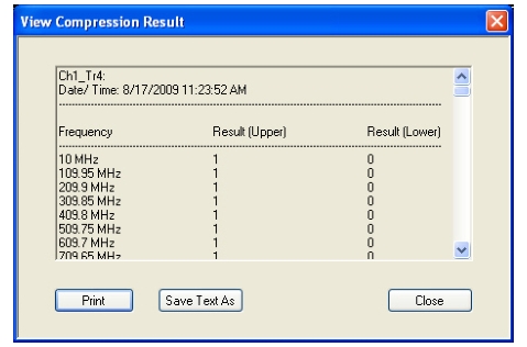
VIEW COMPRESSION RESULT Dialog Box
The VIEW COMPRESSION RESULT dialog box allows review of the compression results.