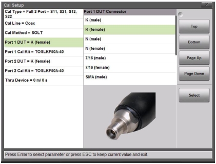
For the most accurate calibrations, you must select the connector of the DUT that will be attached to Port 1 or Port 2 of the instrument. After you select the DUT connector, you must then select the desired calibration kit that will be used for the Port 1 or 2 correction. If you do not select a desired calibration kit, then the analyzer defaults to one of the built‑in kits.
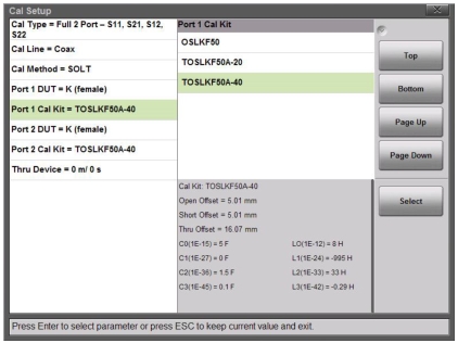
Figure: Selection Window for Port 1 DUT Connector shows the selection window for the Port 1 DUT connector. For easier identification of the DUT connector, a representative picture is shown for each selection. After a connector is chosen, the Port 1 Cal Kit selection is updated in order to list only the available calibration kits that are associated with the selected DUT connector. Figure: Selection Window for Port 1 Cal Kit shows an example of the selection of calibration kits that are available for the K (female) coaxial DUT connector.
For each coaxial kit in the list, the values of the Offset Lengths for the Open, Short, and Thru (if applicable) are listed. The Capacitance and Inductance values for the Open and Short are also listed, as shown in Figure: Selection Window for Port 1 Cal Kit. For waveguide calibration kits, the Cutoff Frequency and the Offset Short 1 and Short 2 lengths are listed.
Selection Window for Port 1 DUT Connector
Figure: Selection Window for Port 1 Cal Kit shows the Selection window for the Port 1 Cal Kit with its list of available calibration kits and the corresponding parameters for each kit.
Selection Window for Port 1 Cal Kit
The selection list for DUT connectors includes all of the common connectors that you may encounter. Table: Coax Dut Connectors and Cal Kits and Table: Waveguide DUT Connectors provide complete lists of Coax and Waveguide connectors and corresponding calibration kits that are selectable through the Cal Setup dialog box.
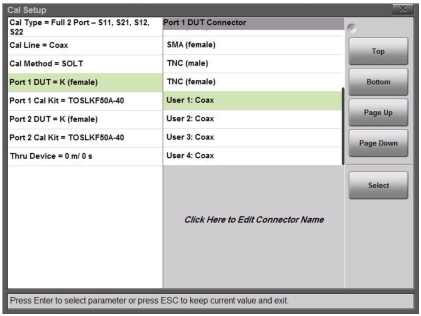
If you are using custom connectors that are not already listed, then the Site Master S820E allows you to create up to ten User DUT connectors and corresponding User Cal Kits. Choose one of the User connectors from the Port 1 DUT Connector list, as shown in Figure: Cal Setup, Port 1 DUT Connectors. You can edit the name of the DUT connector, as indicated on the Site Master screen.
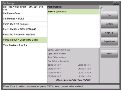
For each User DUT connector, a corresponding User Cal Kit is selected, as shown in Figure: Cal Setup, Port 1 DUT Coax Connector. The coefficients for the calibration kit can be edited, as indicated on the Site Master screen. Customizing the connectors and calibration kit coefficients allows you to have the most flexibility in using any calibration kit that may be required for your measurements.
The user-entered coefficients are retained in the instrument's non-volatile memory and will persist even after the Site Master is powered down or after a Factory Reset. Recalling a setup file will not overwrite the user coefficients.
Caution
To ensure utmost measurement accuracy and consistency, please use the Anritsu calibration kits that are listed in the Calibration menu. These can be found in the accessories section of the S820E technical data sheet. Other Calibration kits that are not listed in the Calibration menu may be used provided you enter the correct required calibration coefficient information under one of the available custom User settings.
Figure: Cal Setup, Port 1 DUT Connectors illustrates the Selection window for the Port 1 DUT connectors, showing the list of custom User connectors available to the user. The name of the connectors can be edited as indicated on the screen.
Cal Setup, Port 1 DUT Connectors
Figure: Cal Setup, Port 1 DUT Coax Connector shows the selection window for the custom User cal kits corresponding to the User 6 DUT coaxial connector. The corresponding cal kit parameters are shown and can be edited as indicated on the screen.