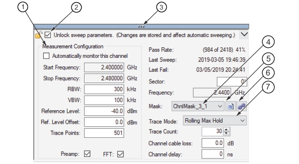
The Measurement Configuration Panel provides trace channel setup and status fields. Refer to Figure: Configuration Panel. The data trace monitoring parameters are set here and are active using the sweep buttons (Sweep Monitors and Sweep Once) in the Trace Acquire menu. See Trace Acquire for trace channel setup details.
Configuration Panel
1. Measurement Configuration Field
2. Unlock sweep parameters
3. Three-Dot-Menu
4. Active Limit Line Mask Button
5. Mask Editor Button
6. Apply Mask to Selected Channel Button
7. Trace Mode Sub-menu Button
Unlock Sweep Parameters
When checked, the Measurement Configuration parameters can be edited. When unchecked, the fields are secured and can not be edited.
Measurement Configuration
Measurement Configuration contains the setup parameters of the spectrum monitor in the field. To change the parameters of the Status Panel, check the Unlock sweep parameters check box. If desired, they can be changed in their respective edit boxes.
Note
The maximum frequency setting Vision provides is the maximum allowed on the measuring instrument up to 54 GHz. Vision does not verify the maximum input frequency range of the measuring instrument.
Start Frequency
The active trace start frequency. Enter Channel start frequency. Press “k” (kHz), “M” (MHz) or “G” (GHz). Range is 9 kHz to maximum range of measuring instrument up to 54 GHz.
Stop Frequency
The active trace stop frequency. Enter Channel stop frequency. Press “k” (kHz), “M” (MHz) or “G” (GHz). Range is 9 kHz to maximum range of measuring instrument up to 54 GHz.
RBW
Set the active trace resolution bandwidth.
VBW
Set the active trace video bandwidth.
Reference Level
The active trace reference level.
Ref. Level Offset
The active trace reference level offset.
Trace Points
The active trace points setting.
Preamp
Check to toggle Preamp to active status for current channel.
FFT
Check to toggle FFT (Fast Fourier Transform) to active status for current channel.
Pass Rate
Provides the total number of traces in the channels, number of traces that passed, and the pass percentage.
Last Sweep
Date and time of the last sweep.
Last Fail
Date and time of the last trace that failed.
Sector
The direction of the antennae in relation to north.
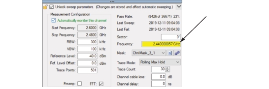
Frequency
The center frequency of the transmission band. This Frequency window highlights yellow when the frequency is not set within the Start and Stop frequency range as shown in Figure: Highlighted Frequency Window.
Highlighted Frequency Window
Mask
From the Mask list, click a limit line mask. Includes “Limit Line Editor” and “Apply Mask to Selected Channel” icons. For a more detailed description of these Mask features, see Setting up a Mask.
Trace Mode
From the Mask list, click active limit line mask. See Trace Mode.
Trace Count
Enter the trace count when Rolling Min Hold or Rolling Max Hold is selected.
When Averaging is set, the trace displayed is the result of the trace count multiplied by each Rolling Min Hold or Rolling Max Hold. Example: Trace count set to 5 will return a trace that is a result of the Rolling Min Hold signal swept 5 times and the resulting average of the 5 sweeps is displayed.
Channel cable loss
Type the channel cable loss. This value sets the cable loss (in dB) for this channel. This value will be subtracted from the measured values.
Channel delay
Type the channel delay. This value sets the wait time for this channel before Trace Acquire determines the monitor non-responsive.