This chapter provides details and procedures about the following calibration methods: InstaCal (ICN51A), Transmission (2-Port, Option 21), Transmission (USB Sensor), Open-Short-Load, Standard Cal and Flex Cal.
Chapter Overview
Refer to the following sections for a better understanding of the calibration:
For the most accurate results possible, the instrument should be calibrated before making any measurements.
OSL calibration components are used with cable and antenna analyzer measurements and are available from Anritsu as optional accessories, refer to your product’s technical data sheet. For transmission measurements, an external USB power sensor is used in the calibration setup and is connected to the instrument with a through test port cable or adapter.
Common RF Terms
3 dB Rule
A 3 dB gain means twice (x2) the power. A 3 dB loss means half the power. For example, a system with 40 watts of input power and a 6 dB insertion loss will only have 10 watts of output power.
dB
Decibel, a logarithm (equal to 10 times) ratio of the difference between two values. The Field Master Series uses dB to measure the ratio of sent signal energy to reflected signal energy. Common values of dB to ratios: 0 dB = 1:1, 10 dB = 10:1, 20 dB = 100:1, 30 dB = 1,000:1, -30 dB = 0.001:1. or (1/1000):1.
dBm
An absolute measurement of power relative to 1 milliwatt. 0 dBm = 1.0 milliwatt, 10 dBm = 10 milliwatt, 30 dBm = (1 mW x 1,000) = 1 watt.
DTF
(Distance to Fault) Measures the location and reflection size of impedance mismatches. This is typically a diagnostic measurement, not a pass/fail judgment measurement. DTF is used to identify and locate faults within an antenna system when the system is failing to meet the specified return loss/VSWR limits. DTF is also useful to verify the total length of a coaxial cable assembly.
Impedance
A measure of an RF components electrical resistance. Measured in ohms (W). In most cable and antenna systems the standard impedance is 50 W.
Insertion Loss
(Cable Loss) Measures the total amount of signal energy absorbed (lost) by the cable assembly. Measured in dB. S21 is another name for this measurement. This is often a pass/fail measurement.
Return Loss
Measurement in dB of reflected energy caused by impedance mismatch. May also be referred to as S11. S11 values are expressed as negative numbers, but Return Loss values are expressed as positive numbers since by definition the “Loss” expression implies a negative sign. The higher the value, the better the impedance match (think of a large negative number being less than a smaller negative number). 40 dB is nearly ideal. Only 0.01% of the total transmitted power is reflected if the Return Loss measurement value is 40 dB. 0 dB would be a complete reflection, or stated another way, 100% of the transmitted power is reflected back. Return Loss is typically a pass/fail measurement.
RF
(Radio Frequency) Frequency of radio sine waves. RF range is 3 kHz to 300 GHz.
VSWR
(Voltage Standing Wave Ratio) Another method to measure reflected energy caused by impedance mismatch. Expressed as a ratio of X:1. VSWR measures the voltage peaks and valleys. 1:1 would be a perfect match. A typical cable and antenna system would be around 1.43:1 or 15 dB Return Loss. The Field Master Series can measure either Return Loss or VSWR. Some carriers require that Return Loss is measured in VSWR. This is typically a pass/fail measurement.
Watt
Unit of measure for power.
Factory Calibration
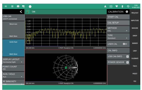
The instrument is calibrated at the factory at room temperature. This default calibration, named 1‑Port ReadyCal is automatically applied to all cable and antenna measurements – except transmission (USB Sensor) measurements – when the instrument has not been manually calibrated or user calibration (User Cal) is turned off.
ReadyCal simplifies the measurement process and can reduce overall test time while maintaining measurement integrity. Anritsu recommends an annual re-calibration at the factory if you routinely apply ReadyCal when making measurements.
When the best possible accuracy is required or the ambient temperature is greatly different from normal room temperature, you should perform a user calibration to override the default ReadyCal. Refer to CALIBRATION Menu.
ReadyCal ON (All Measurements Except Transmission); User Cal Off (Transmission)