Pulse Analyzer Measurement Guide : Pulse Analyzer (Option 421) : Measurement Setup
 
Measurement Setup
Refer to Spectrum Analyzer measurement guide (10580-00447) for basic information on setting up a spectrum measurement. This section provides setup information for the Pulse measurement.
MEASURE Menu
 
MEASURE Menu
 
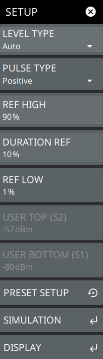
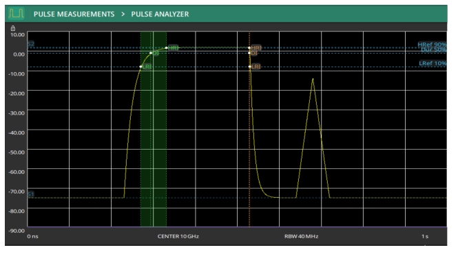
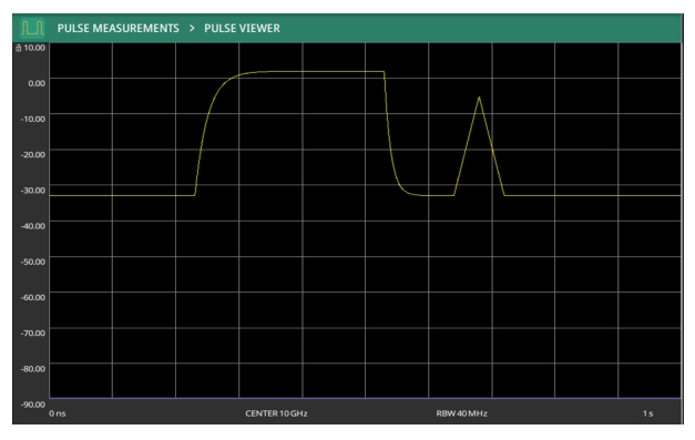
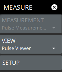
VIEW
Selects Pulse Analyzer or Pulse Viewer.
Pulse Analyzer view provides the signal trace with pulse instant and transition indicators on the trace along with pulse analytics below the trace display. Refer to Pulse Analyzer GUI Overview and Pulse Measurements.
Pulse Viewer displays the signal trace without the pulse instant and transition indicators nor the pulse analytics, and it enables the MARKER menu and faster sweep updates. Refer to Setting Up Markers (Pulse Viewer Mode).
SETUP
Opens the SETUP menu. The SETUP menu can also be accessed directly from the main menu.
SETUP Menu
Pulse SETUP Menu
 
LEVEL TYPE
Selects the desired measurement type from the following list:
Auto: Automatically sets the top and bottom reference levels based on the received signal. See Pulse Measurements.
User: Provides manual setting of the top and bottom reference levels. When se to User, use the USER TOP (S2) and USER BOTTOM (S1) buttons below.
PULSE TYPE
Selects Pulse Type as either positive or negative.
REF HIGH
Sets the high reference level.
DURATION REF
Sets the duration reference level.
REF LOW
Sets the low reference level.
USER TOP (S2)
Used to set the top reference level when LEVEL TYPE is set to User.
USER BOTTOM (S1)
Used to set the bottom reference level when LEVEL TYPE is set to User.
PRESET SETUP
Presets all values on the SETUP menu to default values.
SIMULATION
Opens the PULSE SIMULATION menu. Refer to PULSE SIMULATION Menu.
DISPLAY
Opens the DISPLAY menu. Refer to DISPLAY Menu.
 
PULSE SIMULATION Menu
 
SIMULATION
Toggles pulse simulation on or off. When simulation mode is on, the analyzer stops sweeping and displays an example trace to show the Pulse Analyzer measurement capabilities.
WAVEFORM TYPE
Selects the desired waveform type. You can select a single positive, or a single negative pulse, pulse train, or double pulse. See Figure: Double Pulse Waveform Simulation (Pulse Analyzer View) for a double pulse simulation.
AMP HIGH
sets the upper amplitude of the simulated pulse.
AMP LOW
sets the lower amplitude of the simulated pulse.
PERIOD
sets the period of the simulated pulse.
DUTY FACTOR
sets the duty factor of the simulated pulse.
 
 
Double Pulse Waveform Simulation (Pulse Analyzer View)
 
Double Pulse Waveform Simulation (Pulse Viewer)
DISPLAY Menu
Pulse DISPLAY Menu Markers and Reference Lines Toggles
 
REF HIGH
Toggles the high level reference line on or off.
 
DURATION REF
Toggles the duration reference line on or off.
 
REF LOW
Toggles the low level reference line on or off.
 
POST-T OVER
Toggles the post-transition overshoot marker on or off.
 
POST-T UNDER
Toggles the post-transition undershoot marker on or off.
 
PRE-T OVER
Toggles the pre-transition overshoot marker on or off.
 
PRE-T UNDER
Toggles the pre-transition undershoot marker on or off.
 
S2 HIGH
Toggles the high (S2) reference line on or off.
 
S1 LOW
Toggles the low (S1) reference line on or off.
 
HRI FIRST
Toggles the first-transition high reference instant marker on or off.
 
LRI FIRST
Toggles the first-transition low reference instant marker on or off.
 
DI FIRST
Toggles the first-transition duration instant marker on or off.
 
HRI SECOND
Toggles the second-transition high reference instant marker on or off.
 
LRI SECOND
Toggles the second-transition low reference instant marker on or off.
 
DI SECOND
Toggles the second-transition duration instant marker on or off.