![]() |
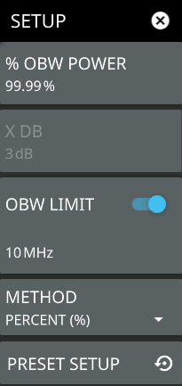
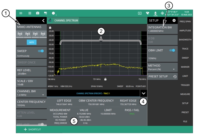
1. LTE Channel Spectrum Analyzer Status Panel: Each measurement features a unique status panel that displays settings and information relevant to the current measurement and view settings. This panel provides quick access to the measurement frequency and band configuration. See Status Panel (LTE Channel Spectrum). 2. Occupied Bandwidth: Occupied bandwidth is integrated over the shaded region where the dashed green lines indicate the upper and lower frequency thresholds. The analyzer will determine and track the occupied bandwidth of the signal within the current span. 3. SETUP Menu: The occupied bandwidth settings are configured in the SETUP menu. See SETUP Menu (LTE Channel Spectrum). 4. Marker frequency values for OBW center, upper and lower frequencies. 5. OBW Summary: This area shows the occupied bandwidth measurement summary data and pass/fail test results, when enabled: • The occupied bandwidth value and the test limit are expressed in frequency units with a pass/fail result. • The total power is integrated over the measured bandwidth and is expressed in dBm. • The received signal power is expressed in dBm. • The transmit signal frequency error is expressed in frequency units (Hz). • Tapping this summary area opens the OBW SETUP menu. |
- ![]() | % OBW POWER Sets the percentage of the total power that is measured within the occupied bandwidth for the current measurement. The resulting occupied bandwidth and total power values are displayed in the measurements results table. X dB Sets the x dB value used for the "x dB bandwidth" measurement. The occupied bandwidth is the frequency range between two points on the signal that are x dB down from the highest signal point within the OBW span. OBW LIMIT Enables limit checking at the specified frequency. The limit test results show as a green PASS or a red FAIL in the measurement table. METHOD Select the measurement method to be PERCENT (%) or X (dB). PRESET SETUP Presets the SETUP menu to default settings. |
![]() | MIMO ANTENNAS: Toggles the current MIMO antenna setting between AUTO or to select one of the available antennas. When a single antenna is selected, a blue underscore will appear below the antenna icon. The antenna icon is highlighted green when receiving a signal. SWEEP: Toggles the current sweep setting between continuously or sweep once. SWEEP ONCE When sweep is set to single sweep, SWEEP ONCE updates the measurement display. Data continues to be captured in the background. REF LEVEL Sets the reference level of the top graticule line in the selected units. If the reference level offset is not zero, OFFSET REF LEVEL is displayed at this location. Refer to Setting Amplitude. SCALE/DIV Sets the graticule scale/division for log-based units. This setting does not apply to linear units. CHANNEL BW Sets the measurement channel bandwidth. The available bandwidth settings depend on the selected band and bandwidth option installed in the instrument. CENTER FREQUENCY Sets the center frequency of the measurement channel. ATTEN LEVEL When auto attenuation is off, sets input attenuation. PRE AMP Toggles the low-noise front-end preamplifier on or off. Refer to Setting Amplitude. TRACES Displays the current status of up to six traces in a quick-view summary. The summary information includes the trace number, type, mode, and detector type. The active trace will show a highlighted background with the mode and detector type restated under the table. Pressing a trace in the summary panel activates the pressed trace and opens the TRACE menu, which allows you to select and set up an individual trace as desired. Refer to Setting Trace Parameters. FREQ REFERENCE Indicates the current frequency reference source of Internal, External, or GNSS (GPS) Hi Accuracy (requires GPS). The instrument automatically selects the frequency reference in the following order of priority: external, GNSS (GPS), then the internal time base. |