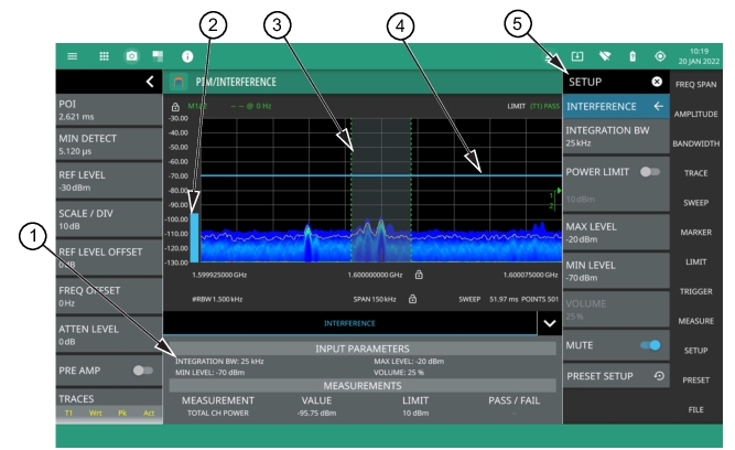
The interference finder measurement is set up using the Interference Menu. The interference finder measurement is used in conjunction with a directional antenna to locate the direction of an interfering signal. This test measures the integrated power of a received signal over a specified frequency range. During the measurement, the instrument emits an audio tone that coincides with the power of the received signal. As the antenna is pointed toward the signal source, the signal level increases further into the set MAX and MIN level, and the audio increases in pitch. An example of a frequency modulated interfering signal is shown in the figure below.
Interference Finder Measurement
1. Interference setup parameters and measurement results are shown in a table at the bottom of the display.
2. A vertical bar corresponds to the received signal strength within the integration bandwidth.
3. Dashed vertical lines and a shaded region define the received channel integration bandwidth.
4. Horizontal blue lines define the audio response range for the measurement.
5. All signal power measurement parameters are set via the SETUP menu.
Frequency and level settings for many interfering signals can be set as follows:
1. Press MEASURE on the main menu.
2. Select Interference from the MEASUREMENT button.
3. Press SETUP and then do the following:
• Set the signal INTEGRATION BW (bandwidth).
• Toggle and set the POWER LIMIT if you wish to see pass/fail test results.
• Set the MAX LEVEL and MIN LEVEL for the audio pitch response of the measurement. Note that these settings can also be dragged into position using the indicator bars in the display panel.
• Set the desired volume level.
Interference Finder is a constant measurement; after it is turned on, it remains on until a different measurement is selected or the sweep is paused. Signal power and a corresponding audio pitch is calculated at the end of each sweep.
Note
Some directional antennas have a narrower null than their forward beam width; therefore, it may be more precise to find the null at the back of the directional antenna to determine the direction of the interfering signal. In this case, you would look for the lowest signal level and the corresponding audio would have the lowest pitch.
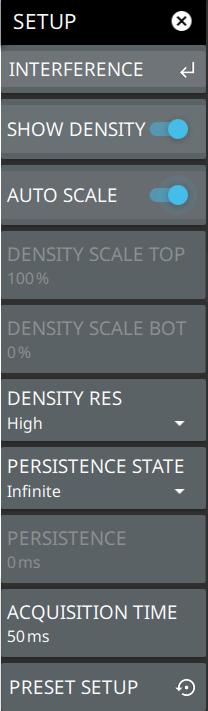
Toggles the density display on or off. Density displays the relative time density of a signal in a color scale ranging from blue to red. Signals that persist longer or more often during the acquisition time are indicated in red color. Brief transient signals are shown in blue color.
AUTOSCALE
When toggled on, automatically adjusts the DENSITY SCALE TOP and DENSITY SCALE BOT settings of the density display based on the amplitude of the signal.
DENSITY SCALE TOP
Sets the percentage of signal time for the top (red) density scale.
DENSITY SCALE BOT
Sets the percentage of signal time for the bottom (blue) density scale. Any signal that appears at a rate lower than the DENSITY SCALE BOT setting will not appear in the density plot.
DENSITY RES
Density resolution sets the FFT size of the RTSA capture. Normal resolution sets a 512 point FFT; High resolution sets a 1024 point FFT. Higher resolution gives finer frequency detail to the density display, but increases POI. Lower resolution will result in a lower POI, but gives less frequency detail to the density display.
PERSISTENCE STATE
Toggles the persistence state between Variable or Infinite. Infinite persistence means the density plot will not fade away after a signal is no longer present. It is useful for seeing very fast and infrequent signals. Variable persistence sets a user defined time for the density colors to fade. Longer persistence values can be used to best illustrate the signals being observed.
PERSISTENCE
Sets the decay time of the density display.
ACQUISITION TIME
The acquisition time sets the update interval for each spectrum trace, spectrogram line, and density display. During the acquisition interval, spectral data from multiple FFTs of the input signal are taken and combined. The acquisition time is adjustable to allow resolving multiple, brief signal events in time and to observe longer term behaviors.
PRESET SETUP
Presets all values on the SETUP menu to default values.
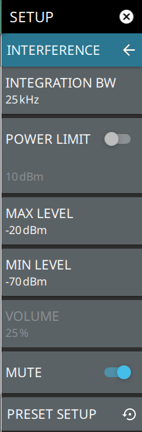
Interference Menu
Interference Menu
INTEGRATION BW
Sets the range of integration used in calculating the received power. The integration bandwidth is displayed as the shaded region between the bandwidth start and stop thresholds (dashed green lines).
POWER LIMIT
The power limit is the threshold value used to determine whether the actual measured channel power will pass or not. If the measured channel power exceeds the set power limit, the channel power test fails; otherwise, the test passes. Pass/fail test results are shown in the measurement results table.
MAX LEVEL
Sets the upper level for the audio response of the measurement. This setting is useful for adjusting the resolution of the tone changes. Power levels above the MAX LEVEL will continue to emit sound an increasingly higher pitch.
MIN LEVEL
Sets the lower level for the audio response of the measurement. The MIN LEVEL also functions as a squelch. Power below this level will not emit a sound.
VOLUME
Sets the volume level for the audio response of the measurement. Note that the system volume can affect the range of this setting. Refer to Interference Finder (Option 24).
MUTE ALL
Mutes the volume of the instrument.
PRESET SETUP
Presets all values on the SETUP menu to default values.
Status Panel (PIM/Interference)
The status panels and features illustrated in this section are unique to the real-time spectrum analyzer and to the selected measurement and view. Below is the Interference status panel that covers RF Spectrum and spectrogram views, in addition to audio AM/FM and interference measurements (selected via MEASURE > MEASUREMENT menu).
Interference Status Panel with minimized Status Panel Icons
-
Pressing editable parameters opens the associated menu with a keypad that allows you to conveniently change the parameter value. These are the same settings found in the right side menus.
POI
Probability of Intercept (POI) is the minimum signal duration that the analyzer can detect at full amplitude with 100% probability.
MIN DETECT
The minimum detection is the minimum signal duration that the analyzer can detect.
VOLUME
Sets the volume level for the audio response of the measurement. Note that the system volume can affect the range of this setting. Refer to Interference Finder (Option 24).
REF LEVEL
Sets the reference level of the top graticule line. If the reference level offset is not zero, OFFSET REF LEVEL is displayed at this location.
Displays the current status of up to six traces or cursors in a quick-view summary. When the measurement view is set to RF Spectrum, trace information is displayed in this area. When the measurement view is set to Spectrogram, cursor information is displayed in this area. Cursors are only available in the RTSA measurement with the Spectrogram view selected.
The summary information includes the trace or cursor number, type, mode, and detector type. The active trace will show a highlighted background with the mode and detector type restated under the table. In Spectrogram, a reference trace (T0) will show you the settings of the trace used to fill the spectrogram. The reference trace settings are applied to all traces and cursors while in Spectrogram view. Pressing a trace or cursor in the summary panel activates the pressed trace or cursor and opens the TRACE menu. It allows you to select and set up an individual trace or cursor as desired. Refer to Setting Trace and Cursor Parameters.
SWEEP
Toggles the current sweep setting between continuously or sweep once. Refer to Setting Sweep Parameters.
FREQ REFERENCE
Indicates the current frequency reference source of Internal High Accuracy (used after GPS has lost sync, but while the internal clock still has good GPS reference), Internal Standard Accuracy, External, or GNSS (GPS) Hi Accuracy (requires GPS). The instrument automatically selects the frequency reference in the following order of priority: external, GPS, then the internal time base.