WCDMA Analyzer Measurement Guide : WCDMA Analyzer (Option 871) : WCDMA Channel Power
 
WCDMA Channel Power
Channel power measurements are one of most common measurements for a radio transmitter. This test measures the output power of a transmitter within the specified channel bandwidth. Out-of-specification power measurements indicate system faults, which can be in the power amplifiers or in filter circuits. Channel power measurements can be used to validate transmitter performance, comply with government regulations, or to keep overall system interference at a minimum.
The channel power measurement is a test performed to measure the power transmitted within a specified frequency or channel bandwidth. The total RF power and power spectral density (PSD) is determined from a channel power measurement. An example of a channel power measurement is shown in Figure: WCDMA Channel Power Measurement.
WCDMA Channel Power Measurement 

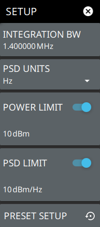
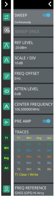
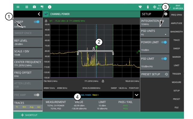
1. WCDMA Analyzer Status Panel: Each measurement features a unique status panel that displays settings and information relevant to the current measurement and view settings. This panel provides quick access to the MIMO antenna selection and status, sweep setting, and frequency and bandwidth configuration. See STATUS PANEL (Channel Power).
2. Channel Power: Channel power is integrated over the shaded region where the dashed green lines indicate the upper and lower frequency thresholds.
3. SETUP Menu: The channel power settings are configured in the SETUP menu. See SETUP Menu (Channel Power).
4. Channel Power Summary: This area shows the channel power measurement summary data and pass/fail test results, when enabled:
The total channel power value and the test limit are expressed in dBm with a pass/fail result.
The total PSD limit is expressed in dBm with a pass/fail result.
Tapping this summary area opens the setup menu..
 
SETUP Menu (Channel Power)
The channel power SETUP menu is available in MEASURE > MEASUREMENT > Channel Power > SETUP. Once the channel power measurement is selected, the SETUP menu can be quickly accessed by tapping on the summary display area below the spectrum display.
WCDMA SETUP Menu (Channel Power)
-
 
INTEGRATION BW
Sets the range of integration used in calculating the power in the channel. The integration bandwidth (IBW) is displayed as the shaded region between the bandwidth start and stop thresholds (dashed green lines).
PSD UNITS
Sets the unit bandwidth for power spectral density (PSD). The available units are Hz or MHz.
POWER LIMIT
The power limit is the threshold value used to determine whether the actual measured channel power will pass or not. If the measured channel power exceeds the set power limit, the channel power test fails; otherwise, the test passes. Pass/fail test results are shown in the measurement results table.
PSD LIMIT
If the power spectral density limit is on, the PSD limit is the threshold value used to determine whether the actual measured PSD will pass or not. If the measured PSD exceeds the PSD limit, the PSD test fails; otherwise the test passes.
PRESET SETUP
Presets the SETUP menu to default settings.
 
STATUS PANEL (Channel Power)
The status panel illustrated in this section is unique to the current analyzer and to the particular measurement and view that is selected.
Figure: Status Panel and Minimized Status Panel Icons (Channel Power) shows the WCDMA status panel that covers the WCDMA channel power measurements.
Status Panel and Minimized Status Panel Icons (Channel Power) 
 
SWEEP: Toggles the current sweep setting between continuously or sweep once.
SWEEP ONCE
When sweep is set to single sweep, SWEEP ONCE updates the measurement display. Data continues to be captured in the background.
REF LEVEL
Sets the reference level of the top graticule line in the selected units. If the reference level offset is not zero, OFFSET REF LEVEL is displayed at this location. Refer to Setting Amplitude.
SCALE/DIV
Sets the graticule scale/division for log-based units. This setting does not apply to linear units.
FREQ OFFSET
Accounts for frequency conversions outside of the analyzer.
ATTEN LEVEL
When auto attenuation is off, sets input attenuation.
CENTER FREQUENCY
Sets the center frequency of the sweep range. The current span setting will remain constant or will be adjusted to accommodate the start and stop frequency range of the instrument. The center frequency can also be dragged on the display when gestures are not toggled off.
PRE AMP
Turns the low-noise front-end preamplifier on or off. To ensure accurate measurement results, the largest signal into the instrument input when the preamplifier is turned on should be less than –40 dBm. The preamplifier cannot be turned on if auto attenuation is on and the reference level is above –40 dBm.
TRACES
Displays the current status of up to six traces in a quick-view summary. The summary information includes the trace number, type, mode, and detector type. The active trace will show a highlighted background with the mode and detector type restated under the table. Pressing a trace in the summary panel activates the pressed trace and opens the TRACE menu, which allows you to select and set up an individual trace as desired. Refer to Setting Sweep Parameters.
FREQ REFERENCE
Indicates the current frequency reference source of Internal, External, or GNSS (GPS) Hi Accuracy (requires GPS). The instrument automatically selects the frequency reference in the following order of priority: external, GNSS (GPS), then the internal time base.