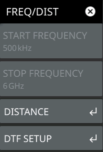
The frequency and distance menu provides access to start and stop settings, and related settings for cable parameters and windowing. The start and stop settings must be made prior to a user calibration. Changing these settings after a calibration will disable the current user calibration and a new calibration will need to be performed.
2. Select START FREQUENCY to open the start frequency parameter entry keypad.
3. Enter the desired start frequency. When entering a frequency with the keypad, available frequency units (GHz, MHz, kHz, and Hz) will be displayed along the right edge of the menu.
4. Select the appropriate frequency unit to terminate the entry or select ACCEPT to terminate the entry with the current frequency unit.
5. Select STOP FREQUENCY to open the stop frequency parameter entry keypad.
6. Enter the desired stop frequency. When entering a frequency with the keypad, available frequency units (GHz, MHz, kHz, and Hz) will be displayed along the right edge of the menu.
7. Select the appropriate frequency unit to terminate the entry or select ACCEPT to terminate the entry with the current frequency unit.
Note
To quickly move the start or stop frequency value up or down, press the + or – slider controls to increment the frequency by the set FREQUENCY STEP. You can also drag the frequency using the slider.
The center frequency will be set to exactly the middle of the start and stop frequencies. The current settings are shown along the bottom of the display graph.
FREQ/DIST Menu
FREQ/DIST Menu
Changing the start or the stop frequency requires turning off User Cal if the active Cal Type is Standard. Use Flex Cal to allow frequency range adjustments with User Cal on. Refer to .
START FREQUENCY
Sets the start frequency of the sweep range. Selecting the plus (+) or minus (–) control moves the start frequency in discrete steps.
STOP FREQUENCY
Sets the stop frequency of the sweep range. Selecting the plus (+) or minus (–) control moves the start frequency in discrete steps.
3. Select START DISTANCE to open the start distance parameter entry keypad.
4. Enter the desired start distance in meters or feet.
5. Select the appropriate distance unit to terminate the entry or press ACCEPT to terminate the entry with the current distance unit.
6. Select STOP DISTANCE to open the stop distance parameter entry keypad.
7. Enter the desired stop distance in meters or feet.
8. Select the appropriate distance unit to terminate the entry or press ACCEPT to terminate the entry with the current frequency unit.
Note
To quickly move the start or stop distance value up or down, press the + or – slider controls to increment the distance in steps. You can also drag the distance using the slider.
The center distance will be set to exactly the middle of the start and stop distance. The current settings are shown along the bottom of the display graph.
9. To access and change other DTF parameters, press DTF AID or DTF SETUP, then select a parameter in the menu to edit.
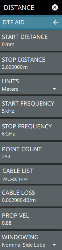
The DTF AID displays DTF info relevant to the current instrument setup and provides dynamic, on-screen guidance for the settings that you access. DTF AID provides most of the distance related parameter settings. The DTF SETUP menu is more condensed and does not display the on-screen guidance.
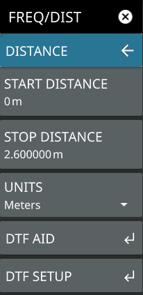
Enters a start distance value for the measurement. The start distance must be shorter than the stop distance.
STOP DISTANCE
Enters the stop distance for the measurement. The maximum stop distance is 1500 m (~4921 ft).
Note that the maximum distance measurement (from start to stop) is dependent on frequency span and the number of sweep points.
UNITS
Selects distance units of meters or feet.
DTF AID
Opens the DTF AID Menu, providing on-screen guidance and access to multiple measurement settings. Also displays current measurement setup information and maximum testing distance and resolution.
Enters a start distance value for the measurement. The start distance must be shorter than the stop distance.
STOP DISTANCE
Enters the stop distance for the measurement. The maximum stop distance is 1500 m.
Note that the maximum distance measurement (from start to stop) is dependent on frequency span and the number of sweep points.
UNITS
Selects distance units of meters or feet.
START FREQUENCY
Sets the start frequency of the sweep range. Selecting the plus (+) or minus (–) control moves the start frequency in discrete steps.
STOP FREQUENCY
Sets the stop frequency of the sweep range. Selecting the plus (+) or minus (–) control moves the start frequency in discrete steps.
POINT COUNT
Sets the number of display point currently measured by the instrument. Note that increasing the number of display points can improve the resolution of measurements in addition to increase in sweep time.
When a cable is selected from this list, propagation velocity and cable loss are automatically set by the instrument. If the preselected values for propagation velocity or cable loss are changed, the analyzer will use “NONE” as the cable type.
CABLE LOSS
Manually enters a cable loss value.
PROP VEL
Manually enters a propagation velocity value.
WINDOWING
Selects the windowing for the measurement:
• Rectangular: Rectangular windowing shows the highest side lobe levels (worst) and the greatest main lobe resolution (best).
• Nominal Side Lobe: Nominal side lobe windowing shows less side lobe levels than rectangular windowing (good) but lower main lobe resolution (very good).
• Low Side Lobe: Low side lobe windowing shows less side lobe levels than nominal windowing (very good) but lower main lobe resolution (good).
• Minimum Side Lobe: Minimum side lobe windowing shows the lowest side lobe levels (best) but the least main lobe resolution (worst).
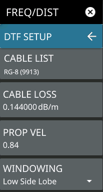
DTF SETUP Menu
DTF SETUP Menu
CABLE LIST
Opens a list of available cable specifications (see Cable List).
When a cable is selected from this list, propagation velocity and cable loss are automatically set by the instrument. If the preselected values for propagation velocity or cable loss are changed, the analyzer will use “NONE” as the cable type.
CABLE LOSS
Manually enters a cable loss value.
PROP VEL
Manually enters a propagation velocity value.
WINDOWING
Selects the windowing for the measurement:
• Rectangular: Rectangular windowing shows the highest side lobe levels (worst) and the greatest main lobe resolution (best).
• Nominal Side Lobe: Nominal side lobe windowing shows less side lobe levels than rectangular windowing (good) but lower main lobe resolution (very good).
• Low Side Lobe: Low side lobe windowing shows less side lobe levels than nominal windowing (very good) but lower main lobe resolution (good).
• Minimum Side Lobe: Minimum side lobe windowing shows the lowest side lobe levels (best) but the least main lobe resolution (worst).