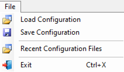
Opens a browse dialog to find and load a configuration file.
Save Configuration
Open to display the saved settings for the MX281000A software that have been recently used. Basic information is stored and subsequently when the same file is opened again it is very fast. Along with the basic file description, user settings such as markers are also stored in the same place.
Recent Configuration Files
Displays the most recent configuration files from the saved configuration folder.
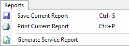
Press to provide the Service Report Generator menu. Use the Service Report Generator dialog to set the testing results print criteria. See Service Report Generator.
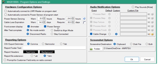
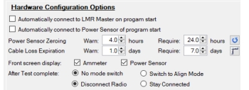
The hardware configuration options provide MA24103A and cable loss re-characterization time settings as shown in Figure: Hardware Configuration Options.
Hardware Configuration Options
\
Automatically connect to LMR Master on program start
The LMR Master needs to be connected into the test configuration. When checked, the program will attempt to connect to the hardware when the program starts. When not checked, the user will need to connect manually.The LMR Master connection can be done manually by pressing the LMR button on the toolbar.
Automatically connect to MA24103A on program start
The MA24103A needs to be connected into the test configuration. When checked, the program will attempt to connect to the hardware when the program starts. When not checked, the user will need to connect manually.The MA24103A connection can be done manually by pressing the MA24103A button on the toolbar.
Power Sensor Zeroing
The MA24103A is required to be zeroed periodically. Zeroing a MA24103A is important to reduce zero offset and noise impact, thereby continually maximizing the accuracy of an RF power measurement.
Warn: (warning): Set time from 1 to 24 hours to inform of the remaining time before power sensor zeroing is required.
Require: Set the time box value from 1 to 96 hours. When the set time set is reached, the testing will not perform calibrations until the cable loss is calibrated.
The indicator is green when operating within the set warning time. Yellow indicates the power sensor zeroing warning time has been reached. but testing can continue. Red indicates time to re-zero the power sensor. Testing will be blocked until the power sensor is zeroed again.
The RF Test Cable requires a cable loss calibration to be performed to compensate impedance mismatch between the load and the internal impedance on a radio frequency (RF) transmission line that may occur when connecting and disconnecting the testing cables. The cable loss calibration should be performed periodically and can be set as follows:
Warn: (warning): Set time from 0.5 to 14 days to inform of the remaining time before cable loss calibration is required.
Require: Set the time box value from 0.5 to 90 days. When the set time set is reached, the testing will not perform calibrations until the cable loss is calibrated.
The indicator is green when operating within the set warning time. Yellow is warning to recalibrate the cable loss, but testing can continue. Red indicates time to recalibrate due to cable loss that may have occurred. Testing will be blocked until the power sensor is zeroed again.
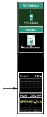
Front Screen Display
Because the measurement screens are unavailable to view when using the test and alignment screens, check the boxes to provide a small screen view of the MA25202A and MA24103A displays on the front screen as shown in Figure: MA25202A and MA24103A Small Screen Display.
MA25202A and MA24103A Small Screen Display
After Test Complete
Set a mode of operation when the test is complete.
No Mode Switch
Stay in Test Mode.
Disconnect Radio
Provides a prompt to disconnect radio when test is complete.
Press to perform the MA24103A zeroing calibration. Zeroing a MA24103A periodically is necessary in order to reduce zero measurement offset and noise impact to improve the accuracy of RF power measurement.
Cable Characterization
Press to perform cable characterization to compensate for test setup cable loss. See Compensating for Cable Loss.
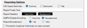
Reporting Options
The Reporting Options menu shown in Figure: Reporting Options provides the generating report preferences.
Reporting Options
CSV Export Delimiter
Set the export file delimiter to Comma, Semicolon, or Tab.
Report Footer Text
Type the text that will appear at the footer of the report. This can be used to identify a testing facility, customer company name, or other identifying report name.
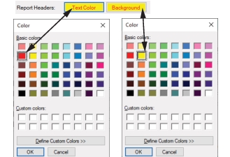
Report Headers
Press the left black box and select a color for the text. Press the right black box to select a color for the background. See Figure: Report Color Palette.
Report Color Palette
Report file extension
Set the file extension of the test results report as .atr (Anritsu Test Report) or .htm.
.atr: The report files can be easily identified using Windows File Explorer, but can only be opened with the MX281000A software.
.htm: The user can share the report by sending an .htm file for anyone to view.
Prompt for Customer Field Entry on Radio Connect
Checking the box displays the Customer Field Entry dialog when the Connect button is pressed. The Connect button is shown in Figure: Connect Button. For more information on using the Customer Entry Field dialog to customize the generated service reports, see Customer Input Fields.
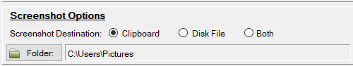
Set the destination of a screenshot capture when using the camera utility. Set the destination as the Clipboard, Disk File, or Both.
Folder
Set the destination folder for the captured images.
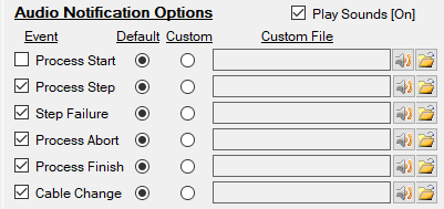
Audio Notification Options Menu
The Audio Notification Options shown in Figure: Audio Notifications Options Menu provides conditional audio sound preferences. Test and alignment can take several minutes to complete. An audible alarm can be set to alert the user of a test status or condition.
Audio Notifications Options Menu
Event
Set the event to sound an audible alarm. The user can set audible alarms with a custom alarm or as off with no audible alarms.
Process Start: An audible alarm sounds when the test is to start.
Process Step: An audible alarm provides notice when a step in the test is complete.
Step Failure: An audible alarm provides notice when the test has failed.
Process Abort: An audible alarm provides notice when the test is aborted.
Process Finish: An audible alarm provides notice when the test is complete.
Cable Change: An audible alarm provides notice when the cable change is requested.
Default
Set the Default radio button to set the default sound.
Custom
Set the Custom radio button to apply a user provided sound from a custom file.
Custom File
Use the folder icon to browse to the folder/file location.
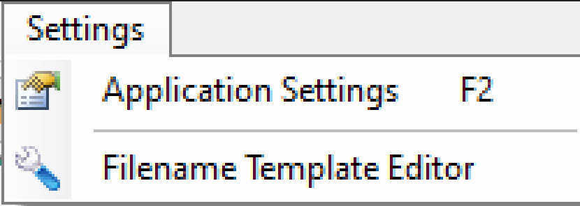
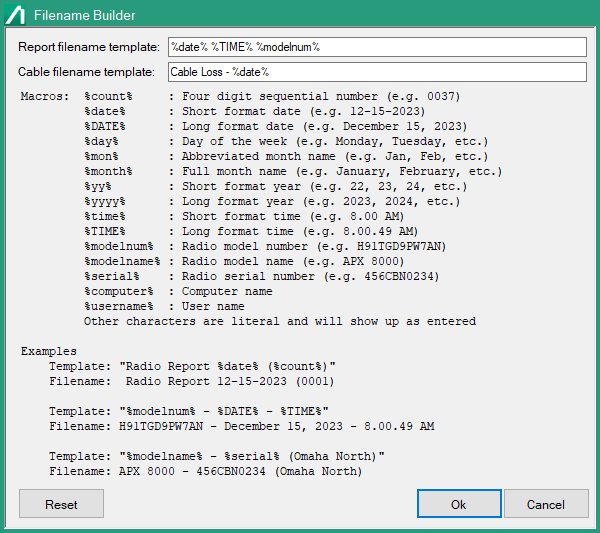
Filename Template Editor
The Filename Template Editor provides the filename template builder shown in Figure: Filename Template Builder. The report file is generated automatically after each auto tune and alignment is performed. Use the Filename Builder to customize the format of the filename for each auto-generated test result. To add a macro into the filename, type the macro shown so it is positioned within the string as required. Refer to the examples in the dialog for template building formats. To remove a macro from the template string, move the mouse over the macro to highlight and then press delete.
Filename Template Builder
Service Report Generator
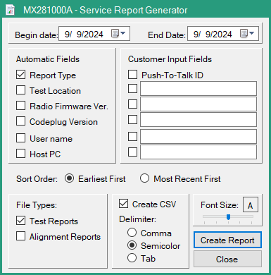
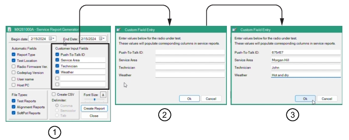
In the menu bar, press Reports and then press Generate Service Report to display the Service Report Generator dialog shown in Figure: Service Report Generator. Here, the user can customize the report by checking the provided informational fields and add up to six user-defined fields. The fields selected format the generated Excel Service Report spreadsheet shown in Figure: Customer Input Fields Dialog Sequence.
Service Report Generator
The default generated columns included in each report are Model number, Name of the radio series, Serial Number of the mobile radio, and Date of the testing. The user selected criteria and columns that will be included in the Service report is described in Figure: Service Report Generator Interface Description.
Service Report Generator Interface Description
-
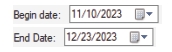
Date Range
Set the Service Report Begin Date and End Date. The spreadsheet will list the tests preformed within the dates selected.
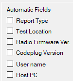
Report Fields
Check the fields that will display in the service report.
Report Type
Displays the testing Type column. This column lists the testing type as Alignment and Test.
Test Location:
Displays the testing Location.
Radio Firmware Version
Displays the Radio Host version.
Codeplug Version
Displays the codeplug file that contains the programming information for the mobile radio.
User Name
Displays the Tester user name.
Host PC:
Displays the Host PC.
Sort Order
Earliest First
Sort by earliest first
Most Recent First
Sort by most recent first
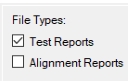
File Types
Check the file type to display in the service report
Test Reports
Displays all the Test reports withing the set date range.
Alignment Reports
Displays all the Alignment reports withing the set date range.
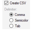
Create CSV
Opens the save browse dialog. Name and save the report as a CSV file.
Delimiter:
Set the delimiter for the Excel spreadsheet columns as Comma, Semicolon, or Tab.
Use the slider to adjust the generated report font size.
Create Report
Press to generate the service report. To print the report, go to the menu bar and press Reports, and then press Print Report to display the print dialog.
Close
Press to close and exit Service Report Generator dialog.
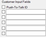
Type in the additional custom fields in the Custom Field Entry dialog. The test pauses and waits for input typed into the added fields from the Customer Input Fields dialog. These entries are used to add up to six columns in the Service Report. Note that the Push to Talk ID is a fixed field that can be completed, but can be ignored if not required to view in the report. In the Customer Fields Entry dialog, type the information required that will appear in the column created. The additional information will appear in the generated Service Report is shown in Figure: Generated Service Report Example.
Customer Input Fields Dialog Sequence
1. Customer Input Fields Dialog
2. Customer Field Entry Dialog
3. Completed Custom Field Entry
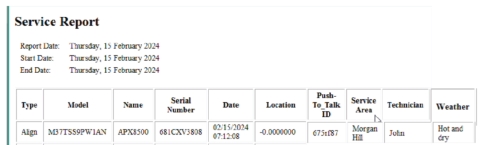
Generated Service Report
The generated Service Report shown in Figure: Generated Service Report Example displays by default the test: Type, Model, Name, Serial Number of the device under test as well as the date of the test and testing status. The additional columns were added as described in Customer Input Fields.