This chapter provides an overview of the MX281000A Auto Test and Alignment software for testing portable and mobile radios. The MX281000A Auto Test and Alignment software provides a user interface that is used with the MA25211A kit for testing and aligning portable and mobile radios.
Testing Procedure
The procedure outlined below provides the basic testing sequence to perform the radio test and alignment described in this chapter.
2. Install the MX281000A Auto Test and Alignment software as described in Software Installation. Once loaded and opened, the opening screen will be displayed as shown in Figure: Opening Screen.
3. Use the opening screen to select a testing mode as described in Mode Menus.
4. In the Mode menus, press the APX Series button to display the main test screen as shown in Figure: APX Test and Alignment Menu. This is the main testing menu. The MX281000A software displays a user interface that provides radio test and report prompts.
5. Characterize the calibration cables as described in Compensating for Cable Loss. Characterizing cable loss is an important process to compensate for the power loss through the test cable in order to optimize the radio testing and alignment.
6. Zero the MA24103A as described in Power Sensor Zeroing. Power sensor zeroing is important to optimize the MA24103A power sensor performance.
7. Use the Settings Menu to set up testing preferences.
8. Connect the LMR Master S412E, ammeter (required for Mobile Test only), and power sensor as described in Test Equipment Status Toolbar. Before testing can begin, all the status LED indicators must be green.
9. Press the Connect button to connect to the radio as shown in Connecting.
11. Create and generate test reports by using the Report tab described in the Menu Bar and the Reports.
Opening Screen
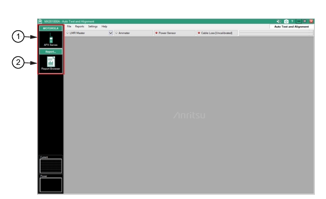
Once the software is installed as described in Software Installation, the opening screen is displayed as shown in Figure: Opening Screen. The testing mode menus are displayed at the top left corner. Use the mouse to click (press) a testing mode and display a mode menu as described in Mode Menus below.
Opening Screen
1. MX281000A Auto Test and Alignment software
2. Testing Mode Menu Tabs
Mode Menus
Press a mode menu to display testing or a reports user interface. The mode menus are shown below.
Motorola Mode
The MOTOROLA mode is shown in Figure: MOTOROLA Mode. This mode menu provides the APX series testing user interface.
MOTOROLA Mode
-
APX Series
Press to display the APX series testing menu. This is the main radio test menu that provides the radio testing interface as shown in Figure: APX Test and Alignment Menu.
Report Mode
The Report mode is shown in Figure: Report Mode. This mode menu provides the Report Browser user interface.
Report Mode
-
Report Browser
Press to display the selected radio test results. The reports types set and printed are described in Reports.