Before testing can begin, the RF Cable Test cable requires a cable loss calibration to be performed to compensate signal loss between the output of the transmitter under test and the power sensor of the test system. Cable loss in the calibration and alignment system must be corrected for as power losses can affect the accuracy of the measurement. The cable loss compensation must be performed periodically to assure the test system power measurements are optimized. Refer to the following cable calibration setups as directed by the software:
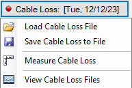
Press the Cable Loss Button to provide a cable loss menu for performing test and alignment measurements. The Cable Loss menu is shown in Figure: Cable Loss Menu.
Cable Loss Menu
Cable Loss
Press to display the cable loss menu. The date refers to the Cable Loss file currently in use.
Load Cable Loss File
Opens the Open file dialog.
Save Cable Loss to file
Open the Save file dialog.
Measure Cable Loss
Press to perform a cable loss measurement. Performs the same function as the Measure Cable Loss icon in Hardware Configuration Icons.
View Cable Loss
Press to view cable loss files.
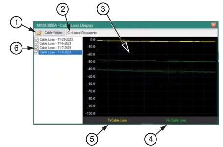
Cable Loss Display
Cable loss files can be viewed and opened to apply to the mobile radio alignment and measurement application. The cable loss display is shown in Figure: Cable Loss Display.
Cable Loss Display
1. Press to open the cable loss folder.
2. Cable loss file path.
3. Previous cable loss data measurements.
4. Indicates the Rx cable loss type when the waveform displayed is green.
5. Indicates the Tx cable loss type when the waveform displayed is yellow.
6. Displays the Cable Loss files in the displayed path folder. Checked opens the data file to view in the window.
Characterizing the Calibration Cable
The calibration cable provides a known characterized cable power loss that is used as a reference when performing the Tx and Rx calibration procedure. Therefore, any cable and equipment path inserted in series with the calibration cable can be measured accurately and therefore adjusted to provide accurate cable loss measurements.
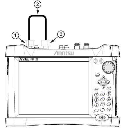
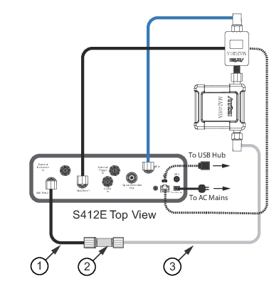
The cable that connects the portable radio and the MA24103A carries the transmitter signal (Tx). The power loss associated with this cable connection must be characterized in order to optimize the radio under test output power measurements. Refer to Figure: APX6000/7000/8000 Tx Cable for the Tx calibration setup.
APX6000/7000/8000 Tx Cable
1. Calibration Cable
2. N-type Barrel Connector (Included with Calibration Cable Assembly)
3. Tx cable (Silver cable that connects mobile radio to MA24103A)
4. Connect to VNA Port 1
5. Connect to VNA Port 2
Procedure
1. Disconnect and remove the Tx cable (silver cable) from the MA24103A and the device under test. This is the Tx cable that is being characterized.
2. Connect one end (the right-angle end if applicable)of the Tx cable to VNA Port 1 of the S412E.
3. Connect the other end of the Tx cable to an N-Type barrel.
4. Connect one end of the calibration cable (this is the cable that was characterized in Characterizing the Calibration Cable) to the open end of the N-Type barrel.
5. Connect the open end of the calibration cable to the VNA Port 2.
6. Press the Next button to perform the Tx cable calibration.
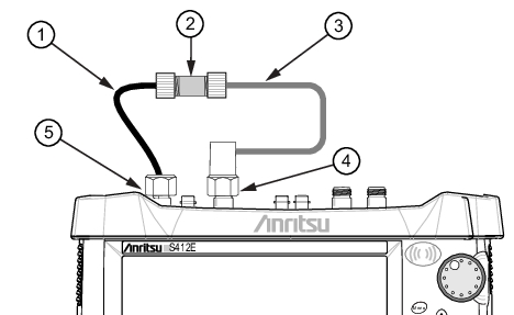
The Rx power loss calibration calibrates the incoming signal path being received from the mobile radio through to the S412E RF input port. The power loss associated with this cable connection must be characterized in order to optimize the radio under test receive power measurements. Refer to Figure: Rx Cable Assembly Calibration for the Rx calibration setup.
Rx Cable Assembly Calibration
1. Calibration Cable
2. N-Type Barrel Adapter
3. Cable from Mobile Radio Connection
Procedure
1. Connect the MA25201A to the LMR Master Port 1.
2. Connect the Tx Cable to the LMR Master VNA Port 2 via the calibration cable and N-Type adapter.
3. Connect the other end of the Tx Cable to the MA24103A.