The appearance and button availability of the calibration menus depends on the settings established in the CAL SETUP, CAL METHOD, LINE TYPE menus and in the associated dialog boxes that appear from the Edit Cal Params button. The Conversion Cal buttons appear when the VNA is configured with Option 7, Receiver Calibration, and is setup for a Mixer measurement.
This button is unavailable until all calibration tasks have been successfully completed. When available, select the button to return to the CALIBRATION menu when the Cal Status is set to ON.
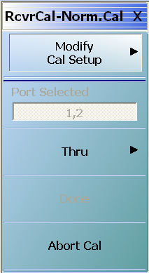
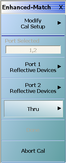
Read-only display of the ports selected for the pending calibration.
Port 1 Reflective Devices
When selected, provides the REFL. DEVICES PORT 1 menu to perform calibration tasks. When all tasks are completed on the menu, returns to the TWO PORT CAL menu.
This button is unavailable until all calibration tasks have been successfully completed. When available, select the button to return to the CALIBRATION menu when the Cal Status is set to ON.
Manual Conversion Cal Setup Dialog Boxes – 2-Port VNAs
From the two RCVRCAL-NORM.CAL and ENHANCED-MATCH conversion cal menus, the Modify Cal Setup button links to the CAL SETUP menu, where the Edit Cal Params button displays the appropriate configuration dialog box that varies depending on the settings made in the MANUAL CAL, CAL SETUP, CAL METHOD, and LINE TYPE menus. Sample dialog boxes are described in the sections below for:
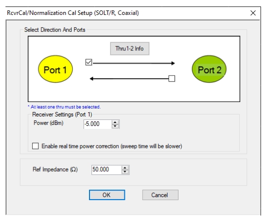
• MAIN | Calibration | CALIBRATION | Calibrate | CALIBRATE | Manual Cal | MANUAL CAL | Rcvr Cal/Normalization | RCVRCAL-NORM.CAL | Modify Cal Setup | CAL SETUP | Edit Cal Params | RCVRCAL/NORMALIZATION CAL SETUP (SOLT/R, Coaxial) Dialog Box
Edit Cal Params – RCVRCAL/NORMALIZATION CAL SETUP (SOLT/R, Coaxial) Dialog Box
Each Rcvr Cal/Normalization Cal Setup dialogs are similar to the example above. To view each dialog box, set the CAL METHOD and LINE TYPE menus to the appropriate settings, and then select the Edit Cal Params button. All dialog boxes are named “RcvrCal/Normalization Cal Setup (Cal Method, Line Type)
Select Direction and Ports
Select at least one port and through path direction.
Ref Impedance (Ω)
Input the reference impedance.
• Input field defaults to 50 Ohms.
• Any numerical value accepted, although input values < 0.01 Ohms are converted to 0.01 Ohms.
ENHANCED-MATCH CAL SETUP (SOLT/R, Coaxial) Dialog Box
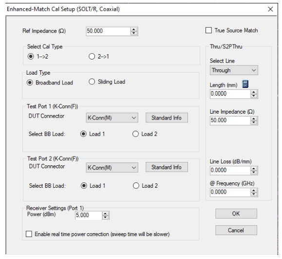
• MAIN | Calibration | CALIBRATION | Calibrate | CALIBRATE | Manual Cal | MANUAL CAL | Rcvr Cal/Normalization | RCVRCAL-NORM.CAL | Modify Cal Setup | CAL SETUP | Edit Cal Params | ENHANCED-MATCH CAL SETUP (SOLT/R, Coaxial) Dialog Box
Edit Cal Params – ENHANCED-MATCH CAL SETUP (SOLT/R, Coaxial) Dialog Box
Reference Impedance
Input the reference impedance and select if a True Source Match (True Source Match is decoupled from the reference impedance when a more comprehensive source match model should be used, usually for millimeter wave mixer setups at the expense of longer calibration time).
• Input field defaulted to 50 Ohms.
• Any numerical value accepted, although input values < 0.01 Ohms are converted to 0.01 Ohms.
Select Cal Type
Select from two radio button controlled options:
• (1 → 2)
• (2 → 1)
Load Type Area
Select from two radio button controlled options:
• Broadband Load
• Sliding Load. If Sliding Load is selected:
• A message appears in the “Still requires broadband loads below sliding load breakpoint frequency.”
• A Sliding Load button appears on the PORT 1 REFLECTIVE DEVICES menu and on the PORT 2 REFLECTIVE DEVICES menu.
Test Port 1 Connector Type Area
Select the DUT Connector Type from a drop-down menu list with options of:
• 0.8 mm-Conn (M)
• 0.8 mm-Conn (F)
• W1-Conn (M)
• W1-Conn (F)
• V-Conn (M)
• V-Conn (F)
• K-Conn (M)
• K-Conn (F)
• 2.4 mm (M)
• 2.4 mm (F)
• GPC-3.5 (M)
• GPC-3.5 (F)
• SMA (M)
• SMA (F)
• N-Conn (M)
• N-Conn (F)
• N-Conn (75) (M)
• N-Conn (75) (F)
• GPC-7
• 7/16 (M)
• 7/16 (F)
• TNC (M) (Kit from Maury Microwave)
• TNC (F) (Kit from Maury Microwave)
• User-Defined1 (M) through User-Defined32 (M)
• User-Defined1 (F) through User-Defined32 (F)
Select BB Load for Test Port 1 Area
Select BB Load number for Test Port 1:
• Load 1
• Load 2
Test Port 1 Connector Standard Info Button
Select displays the STANDARD INFO dialog box for the selected connector and calibration method that displays the connector calibration coefficients. The dialog box contents depends on the connector selected above and on the Cal Method selected.
Test Port 2 Connector Type Area
Select the DUT Connector Type from a drop-down menu list with options the same as the Test Port 1 Connector area above.
Test Port 2 Connector Standard Info Button
Select displays the STANDARD INFO dialog box for the selected connector and calibration method that displays the connector calibration coefficients. The dialog box contents depends on the connector selected above and on the Cal Method selected.
Select BB Load for Test Port 2 Area
Select BB Load number for Test Port 2:
• Load 1
• Load 2
Through Area
Located on the right side of the dialog box, these controls allow characterization of the through/reciprocal line settings.
• Select Line
• Through
• Length (mm)
• Input line length in mm.
• Calculator icon displays the AIR EQUIVALENT LENGTH CONVERSION dialog box.
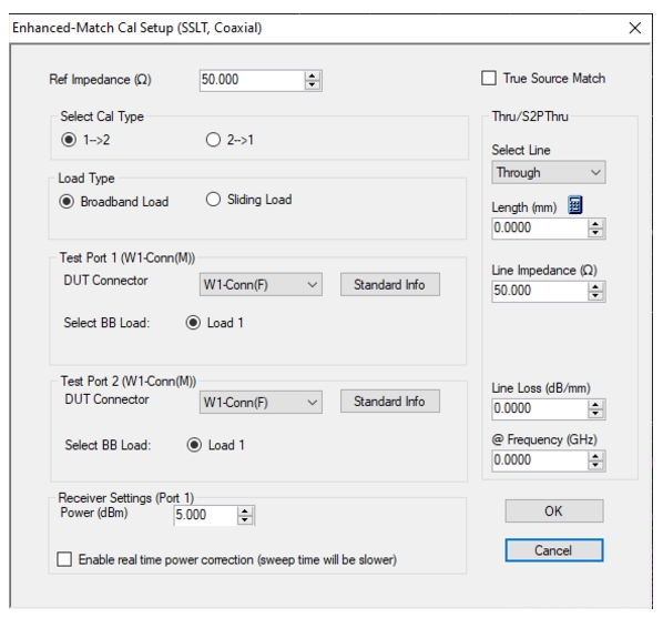
• MAIN | Calibration | CALIBRATION | Calibrate | CALIBRATE | Manual Cal | MANUAL CAL | Rcvr Cal/Normalization | RCVRCAL-NORM.CAL | Modify Cal Setup | CAL SETUP | Edit Cal Params | ENHANCED-MATCH CAL SETUP (SSLT, Coaxial) Dialog Box
ENHANCED-MATCH CAL SETUP (SSLT, Coaxial) Dialog Box
Reference Impedance
Input the reference impedance and select if a True Source Match (True Source Match is decoupled from the reference impedance when a more comprehensive source match model should be used, usually for millimeter wave mixer setups at the expense of longer calibration time).
• Input field defaulted to 50 Ohms.
• Any numerical value accepted, although input values < 0.01 Ohms are converted to 0.01 Ohms.
Select Cal Type
Select from three radio button controlled options:
• (1 → 2)
• (2 → 1)
Load Type Area
Select from two radio button controlled options:
• Broadband Load
• Sliding Load. If Sliding Load is selected:
• A message appears in the “Still requires broadband loads below sliding load breakpoint frequency.”
• A Sliding Load button appears on the PORT 1 REFLECTIVE DEVICES menu and on the PORT 2 REFLECTIVE DEVICES menu.
Test Port 1 Connector Type Area
Select the DUT Connector Type from a drop-down menu list with options of:
• 0.8 mm-Conn (M)
• 0.8 mm-Conn (F)
• W1-Conn (M)
• W1-Conn (F)
• User-Defined1 (M) through User-Defined32 (M)
• User-Defined1 (F) through User-Defined32 (F)
Select BB Load for Test Port 1 Area
Select BB Load number for Test Port 1:
• Load 1
• Load 2
Test Port 1 Connector Standard Info Button
Select displays the STANDARD INFO dialog box for the selected connector and calibration method that displays the connector calibration coefficients. The dialog box contents depends on the connector selected above and on the Cal Method selected.
Test Port 2 Connector Type Area
Select the DUT Connector Type from a drop-down menu list with options the same as the Test Port 1 Connector area above.
Test Port 2 Connector Standard Info Button
Select displays the STANDARD INFO dialog box for the selected connector and calibration method that displays the connector calibration coefficients. The dialog box contents depends on the connector selected above and on the Cal Method selected.
Select BB Load for Test Port 2 Area
Select BB Load number for Test Port 2:
• Load 1
• Load 2
Through Area
Located on the right side of the dialog box, these controls allow characterization of the through/reciprocal line settings.
• Select Line
• Through
• Length (mm)
• Input line length in mm.
• Calculator icon displays the AIR EQUIVALENT LENGTH CONVERSION dialog box.
• Line Impedance (Ohms)
• Input defaults to be 50 Ohms. Any numeric value accepted.
• Line Loss (dB/mm)
• Allows input of a line loss in dB per mm at the frequency specified in the field below.
• @ Frequency (GHz)
• Allows input of a frequency setting for the Line Loss factor input above.
OK / Cancel
Click OK to accept the changes and return to the CAL SETUP menu.
Click Cancel to abandon any changes and return to the CAL SETUP menu.
ENHANCED-MATCH CAL SETUP (SSST, Coaxial) Dialog Box – 2-Port VNA
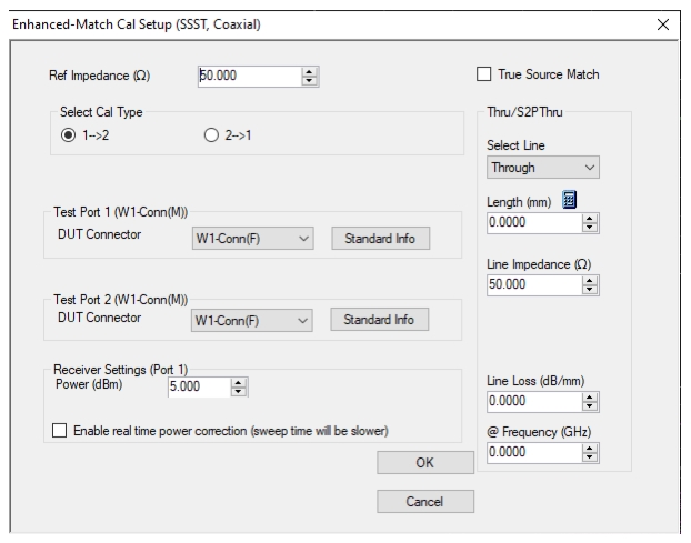
• MAIN | Calibration | CALIBRATION | Calibrate | CALIBRATE | Manual Cal | MANUAL CAL | Rcvr Cal/Normalization | RCVRCAL-NORM.CAL | Modify Cal Setup | CAL SETUP | Edit Cal Params | ENHANCED-MATCH CAL SETUP (SSST, Coaxial) Dialog Box
ENHANCED-MATCH CAL SETUP (SSST, Coaxial) Dialog Box
Reference Impedance
Input the reference impedance and select if a True Source Match (True Source Match is decoupled from the reference impedance when a more comprehensive source match model should be used, usually for millimeter wave mixer setups at the expense of longer calibration time).
• Input field defaulted to 50 Ohms.
• Any numerical value accepted, although input values < 0.01 Ohms are converted to 0.01 Ohms.
Select Cal Type
Select from three radio button controlled options:
• (1 → 2)
• (2 → 1)
Test Port 1 Connector Type Area
Select the DUT Connector Type from a drop-down menu list with options of:
• 0.8 mm-Conn (M)
• 0.8 mm-Conn (F)
• W1-Conn (M)
• W1-Conn (F)
• User-Defined1 (M) through User-Defined32 (M)
• User-Defined1 (F) through User-Defined32 (F)
Test Port 1 Connector Standard Info Button
Select displays the STANDARD INFO dialog box for the selected connector and calibration method that displays the connector calibration coefficients. The dialog box contents depends on the connector selected above and on the Cal Method selected.
Test Port 2 Connector Type Area
Select the DUT Connector Type from a drop-down menu list with options the same as the Test Port 1 Connector area above.
Test Port 2 Connector Standard Info Button
Select displays the STANDARD INFO dialog box for the selected connector and calibration method that displays the connector calibration coefficients. The dialog box contents depends on the connector selected above and on the Cal Method selected.
Through Area
Located on the right side of the dialog box, these controls allow characterization of the through/reciprocal line settings.
• Select Line
• Through
• Length (mm)
• Input line length in mm.
• Calculator icon displays the AIR EQUIVALENT LENGTH CONVERSION dialog box.
• Line Impedance (Ohms)
• Input defaults to be 50 Ohms. Any numeric value accepted.
• Line Loss (dB/mm)
• Allows input of a line loss in dB per mm at the frequency specified in the field below.
• @ Frequency (GHz)
• Allows input of a frequency setting for the Line Loss factor input above.
OK / Cancel
Click OK to accept the changes and return to the CAL SETUP menu.
Click Cancel to abandon any changes and return to the CAL SETUP menu.
Enhanced-Match Cal Setup Dialog Box Summary
The table below summarizes the available fields in all enhanced-match calibration setup dialog boxes. If the dialog box is described above, a link is provided to that description. To view each dialog box, set the CAL METHOD and LINE TYPE menus to the appropriate settings, and then select the Edit Cal Params button. All dialog boxes are named “Enhanced-Match Cal Setup (Cal Method, Line Type)”
Enhanced-Match Cal Setup Dialog Box Summary – 2-Port VNAs (1 of 4)
Test Port 1 and Test Port 2 controls are the same.
Test Port DUT Connector: For each selected test port, select one of the following connectors: 0.8 mm-Conn (M), 0.8 mm-Conn (F), W1-Conn (M), W1-Conn (F), V-Conn (M), V-Conn (F), K-Conn (M), K-Conn (F), 2.4 mm (M), 2.4 mm (F), GPC-3.5 (M), GPC-3.5 (F), SMA (M), SMA (F), N-Conn (M), N-Conn (F), N-Conn (75) (M), N-Conn (75) (F), GPC-7, 7/16 (M), 7/16 (F), TNC (M), TNC (F), User-Defined1 (M) through User-Defined32 (M), User-Defined1 (F) through User-Defined32 (F)
Test Port Connector Standard Info Button: For each DUT port connector, displays the STANDARD INFORMATION or USER-DEFINED dialog box for the selected connector.
Test Port 1 and Test Port 2 controls are the same.
Test Port DUT Connector: For each test port, select one of the following connectors: 0.8 mm-Conn (M), 0.8 mm-Conn (F), W1-Conn (M), W1-Conn (F), User-Defined 1 (M) through User-Defined 32 (M), User-Defined 1 (F) through User-Defined 32 (F)
Test Port Connector Standard Info Button: For each DUT port connector, displays the STANDARD INFORMATION or USER-DEFINED dialog box for the selected connector.