The menus in this section are example menus for the calibration step procedures. The exact content and presence of each menu is dependent on the settings for each calibration run.
REFL. DEVICE(S) Menu – 2-Port VNAs
This menu example is a representative menu based on the following configuration:
• VNA is in 2-port mode
• A 2-port calibration
• A SOLT/SOLR calibration method
• A coaxial line type
• A V (f) Connector
Using a different configuration set can change the appearance of the REFL. DEVICE(S) menu.
Full Name
Reflective Device(s)
Previous
• The previous menu can be any of the following manual calibration menus and their associated configuration dialog boxes.
• The REFL. DEVICE(S) Port 1 menu is nearly identical to the typical REFL. DEVICE(S) Port 2 menu (not shown).
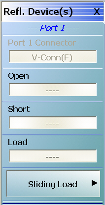
REFL. DEVICE(S) (REFLECTIVE DEVICES) Menu – 2-Port VNAs – Typical Example
A typical REFL. DEVICE(S) menu.
Each button is a completion task button and marked with a checkmark when the calibration task is complete.
Port 1 Connector
A read only button showing the configured connector for the indicated port.
Open
In general, prepare the indicated connections and components and then select the button. Starts the open calibration procedure for the indicated port. When the calibration task is completed, the button is marked with a checkmark.
Short
Starts the short calibration procedure for the indicated port. When the calibration task is completed, the button is marked with a checkmark.
Load
Starts the load calibration procedure for the indicated port. When the calibration task is completed, the button is marked with a checkmark.
Sliding Load
If present, selecting this button displays the SLIDING LOADS menu which is described in the section below.
• The LINES/MATCHES Port 1 menu is nearly identical to typical LINES/MATCHES Port 2, LINES/MATCHES Port 3, and LINES/MATCHES Port 4 menus.
Navigation
• MAIN | Calibration | CALIBRATION | Calibrate | CALIBRATE | Manual Cal | MANUAL CAL | [# of Ports] Cal | [NUM OF PORTS] CAL | Port X-Y Lines/Matches |
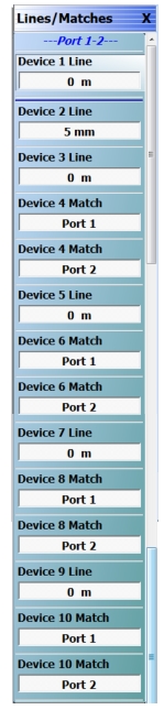
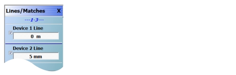
LINES/MATCHES Menu – 2-Port VNAs – Typical Example
Typical LINES/MATCHES menu
When Cal Method selected is TRL/TRM, LRL/LRM, or mTRl, this menu offers selections in accordance with the settings made in the 2 Port Cal Setup Dialog.
Each button on the menu is a completion task button and is marked with a checkmark when the calibration task is complete.
Device 1 Line
In general, prepare the indicated connections and components and then select the button. This starts the calibration procedure for the indicated port. When the calibration task is completed, the button is marked with a checkmark.
Device 2 Line Select the button as above for the calibration procedure.
Device 3 Line Select the button as above for the calibration procedure.
Device 4 Match (Port 1) Select the button as above for the calibration procedure.
Device 4 Match (Port 2) Select the button as above for the calibration procedure.
Device 5 Line Select the button as above for the calibration procedure.
Device 6 Match (Port 1) Select the button as above for the calibration procedure.
Device 6 Match (Port 2) Select the button as above for the calibration procedure.
Device 7 Line Select the button as above for the calibration procedure.
Device 8 Match (Port 1) Select the button as above for the calibration procedure.
Device 8 Match (Port 2) Select the button as above for the calibration procedure.
Device 9 Line Select the button as above for the calibration procedure.
Device 10 Match (Port 1) Select the button as above for the calibration procedure.
Device 10 Match (Port 2) Select the button as above for the calibration procedure.
SLIDING LOADS Menu – 2-Port VNA
This menu example is a representative menu based on the following configuration:
• VNA is in 2-port mode
• A 2-port calibration
• A SOLT/SOLR calibration method
• Sliding loads selected
• A coaxial line type
• A V (f) Connector
Using a different configuration set can change the appearance of the SLIDING LOADS menu.
Previous
• The previous menu can be any of the following manual calibration menus and their associated configuration dialog boxes.
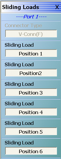
SLIDING LOADS Menu – 2-Port VNAs – Typical Example
A typical SLIDING LOADS menu.
Each button is a completion task button and marked with a checkmark when the calibration task is complete. The number of buttons appearing on the menu is dependent on the calibration settings.
Connector Type
A read only button showing the configured connector for the indicated port.
Sliding Load (Position 1)
In general, prepare the indicated connections and components and then select the button. Starts the sliding load calibration procedure at position 1 for the indicated port. When the calibration task is completed, the button is marked with a checkmark.
Sliding Load (Position 2)
As above for sliding load calibration procedure at position 2.
Sliding Load (Position 3)
As above for sliding load calibration procedure at position 3.
Sliding Load (Position 4)
As above for sliding load calibration procedure at position 4.
Sliding Load (Position 5)
As above for sliding load calibration procedure at position 5.
Sliding Load (Position 6)
As above for sliding load calibration procedure at position 6.
When all calibration procedures are complete, use the Back button to return to the REFL DEVICE menu.
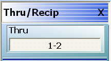
Each button is a completion task button and marked with a checkmark when the calibration task is complete.
Thru (Port Pair 1-2)
In general, prepare the indicated connections and components and then select the button. Starts the through calibration procedure for the indicated port pair. When the calibration task is completed, the button is marked with a checkmark.
When all calibration procedures are complete, use the Back button to return to the REFL DEVICE menu.
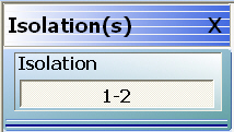
Each button is a completion task button and marked with a checkmark when the calibration task is complete.
Isolation (Port Pair 1-2)
In general, prepare the indicated connections and components and then select the button. Starts the optional isolation calibration procedure for the indicated port pair. When the calibration task is completed, the button is marked with a checkmark.
When all calibration procedures are complete, use the Back button to return to the REFL DEVICE menu.
 .
.