 | |
| |
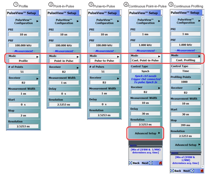
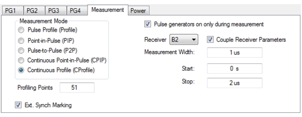
 | PulseView Configuration PRI Pulse Repetition Interval – Sets the primary clock sync pulse period in units of time and is inversely proportional to the pulse repetition frequency (PRI = 1 / PRF). PRI can also be set in the PULSEVIEW CONFIGURATION Dialog Box. PRF Pulse Repetition Frequency – Sets the primary clock sync pulse repetition rate in units of hertz and is inversely proportional to the pulse repetition interval (PRF = 1 / PRI). PRF can also be set in the PULSEVIEW CONFIGURATION Dialog Box. Mode Opens the PULSE MODE Menu to select the pulse mode: Profiling, Point-in-Pulse, Pulse-to-Pulse, Continuous Point-in-Pulse, and Continuous Profiling. Note: The bottom trace display status bar indicates the PulseView pulse mode.  # of Points Sets the number of measurement points from the Start to the Stop time settings. The number of points setting only applies to the Pulse Profile and Continuous Profiling measurement modes. Receiver Selects a receiver channel to configure. Measurement Width Sets the measurement width time (aperture). Start Time Enter a time to wait relative to T0 before measuring a pulse. The start time setting only applies to the pulse profile measurement mode. Stop Time Enter a time relative to T0 at which the measurement should stop. The stop time setting only applies to the pulse profile measurement mode. Resolution Enter a time to allow configuration of the pulse acquisition rate. This allows the user to speed up the measurements by changing the acquisition rate. This is useful when measurements are made at lower rep rates which may not require a high resolution. |
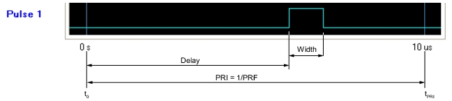
Note | T0 marks the beginning of each primary clock period. All Delay, Width, and the PRI parameter resolutions are limited to increments of 2.5 ns. |
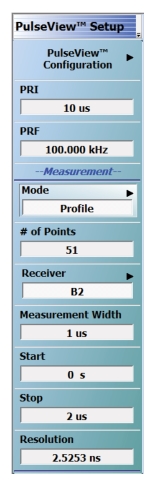
 | PulseView Configuration PRI Pulse Repetition Interval – Sets the primary clock sync pulse period in units of time and is inversely proportional to the pulse repetition frequency (PRI = 1 / PRF). PRI can also be set in the PULSEVIEW CONFIGURATION Dialog Box. PRF Pulse Repetition Frequency – Sets the primary clock sync pulse repetition rate in units of hertz and is inversely proportional to the pulse repetition interval (PRF = 1 / PRI). PRF can also be set in the PULSEVIEW CONFIGURATION Dialog Box. Mode Opens the PULSE MODE Menu to select the pulse mode: Profiling, Point-in-Pulse, Pulse-to-Pulse, Continuous Point-in-Pulse, and Continuous Profiling. Note: the bottom trace display status bar indicates the PulseView pulse mode.  Receiver Selects a receiver channel to configure. Measurement Width Sets the measurement width time (aperture). Delay Enter a time relative to T0 before starting the measurement. The delay time setting applies to point-in-pulse and pulse-to-pulse measurement modes only. Resolution Enter a time to allow configuration of the pulse acquisition rate. This allows the user to speed up the measurements by changing the acquisition rate. This is useful when measurements are made at lower rep rates which may not require a high resolution. |
Note | T0 marks the beginning of each primary clock period. All Delay, Width, and the PRI parameter resolutions are limited to increments of 2.5 ns. |
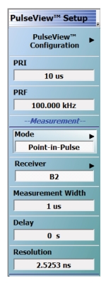
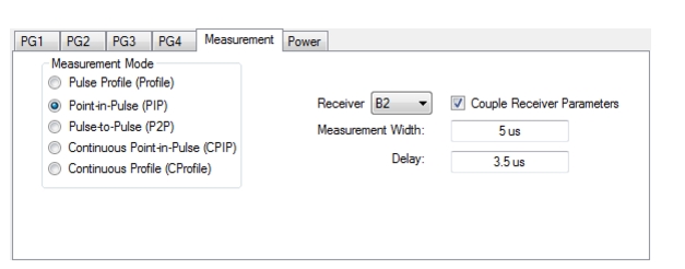
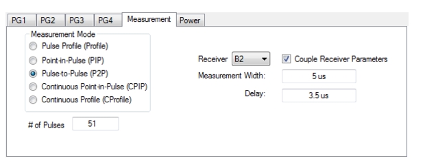
 | PulseView Configuration PRI Pulse Repetition Interval – Sets the primary clock sync pulse period in units of time and is inversely proportional to the pulse repetition frequency (PRI = 1 / PRF). PRI can also be set in the PULSEVIEW CONFIGURATION Dialog Box. PRF Pulse Repetition Frequency – Sets the primary clock sync pulse repetition rate in units of hertz and is inversely proportional to the pulse repetition interval (PRF = 1 / PRI). PRF can also be set in the PULSEVIEW CONFIGURATION Dialog Box. Mode Opens the PULSE MODE Menu to select the pulse mode: Profiling, Point-in-Pulse, Pulse-to-Pulse, Continuous Point-in-Pulse, and Continuous Profiling. Note: The bottom trace display status bar indicates the PulseView pulse mode  # of Pulses Sets the number of pulse measurements to acquire. The number of pulses setting only applies to the pulse-to-pulse measurement mode. Receiver Selects a receiver channel to configure. Measurement Width Sets the measurement width time (aperture). Delay Enter a time relative to T0 before starting the measurement. The delay time setting applies to point-in-pulse and pulse-to-pulse measurement modes only. Resolution Enter a time to allow configuration of the pulse acquisition rate. This allows the user to speed up the measurements by changing the acquisition rate. This is useful when measurements are made at lower rep rates which may not require a high resolution. |
Note | T0 marks the beginning of each primary clock period. All Delay, Width, and the PRI parameter resolutions are limited to increments of 2.5 ns. |
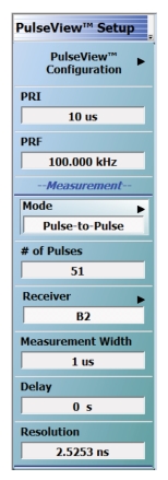
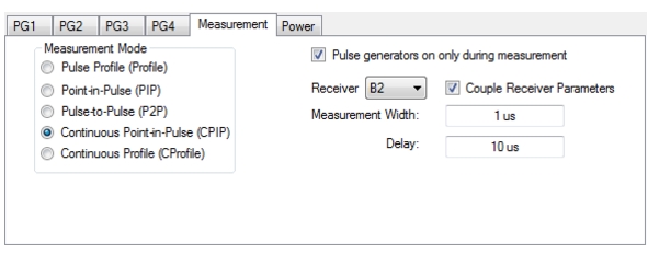
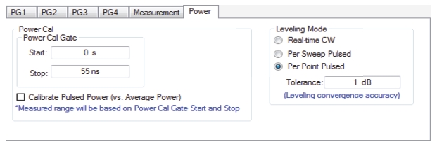
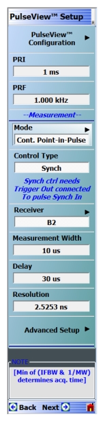 | PulseView Configuration PRI Pulse Repetition Interval – Sets the primary clock sync pulse period in units of time and is inversely proportional to the pulse repetition frequency (PRI = 1 / PRF). PRI can also be set in the PULSEVIEW CONFIGURATION Dialog Box. Note: PRI is limited to limited to a minimum of 100 μs for Synch mode and 1 ms for Time mode Control Types PRF Pulse Repetition Frequency – Sets the primary clock sync pulse repetition rate in units of hertz and is inversely proportional to the pulse repetition interval (PRF = 1 / PRI). PRF can also be set in the PULSEVIEW CONFIGURATION Dialog Box. Mode Opens the PULSE MODE Menu to select the pulse mode: Profiling, Point-in-Pulse, Pulse-to-Pulse, Continuous Point-in-Pulse, and Continuous Profiling. Note: The bottom trace display status bar indicates the PulseView pulse mode.  Control Type Enabled only in CPIP or CProf modes. Choices are Sync and Time. Synch control requires that Trigger Out be connected to Pulse Synch In. This is noted with a tool tip that appears when the pointer is over the Control Type button as well as over the Pulse Configuration dialog button. Receiver Selects a receiver channel to configure. Measurement Width Sets the measurement width time (aperture). Delay Enter a time relative to T0 before starting the measurement. The delay time setting applies to point-in-pulse and pulse-to-pulse measurement modes only. Note: In CPIP mode, minimum delay is 10 μs Resolution Enter a time to allow configuration of the pulse acquisition rate. This allows the user to speed up the measurements by changing the acquisition rate. This is useful when measurements are made at lower rep rates which may not require a high resolution. Advanced Setup Allows user to override the calculated capture duration. See ADVANCED SETUP Menu |
Note | T0 marks the beginning of each primary clock period. All Delay, Width, and the PRI parameter resolutions are limited to increments of 2.5 ns. |
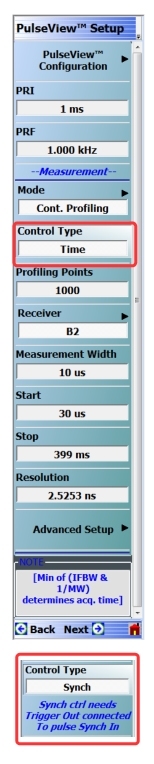 | PulseView Configuration PRI Pulse Repetition Interval – Sets the primary clock sync pulse period in units of time and is inversely proportional to the pulse repetition frequency (PRI = 1 / PRF). PRI can also be set in the PULSEVIEW CONFIGURATION Dialog Box. Note: PRI is limited to limited to a minimum of 100 μs for Synch mode and 1 ms for Time mode Control Types PRF Pulse Repetition Frequency – Sets the primary clock sync pulse repetition rate in units of hertz and is inversely proportional to the pulse repetition interval (PRF = 1 / PRI). PRF can also be set in the PULSEVIEW CONFIGURATION Dialog Box. Mode Opens the PULSE MODE Menu to select the pulse mode: Profiling, Point-in-Pulse, Pulse-to-Pulse, Continuous Point-in-Pulse, and Continuous Profiling. The bottom trace display status bar indicates the PulseView pulse mode:  Control Type Appears only in CPIP or CProf mode. Selecting Control Type toggles between Time and Synch. When Synch is toggled, a notification appears saying “Synch ctrl needs Trigger Out connected to Pulse Synch In” See encircled images at left. Profiling Points Sets the number of displayed analysis points from the Start to the Stop time settings. This can be greater or less than the # of sweep points. Applies only to CProf mode. Receiver – Selects a receiver channel to configure. Measurement Width – Sets the measurement width time (aperture). Start Time Enter a time to wait relative to T0 before measuring a pulse. The start time setting only applies to the pulse profile measurement mode. Stop Time Enter a time relative to T0 at which the measurement should stop. The stop time setting only applies to the pulse profile measurement mode. (Note: T0 marks the beginning of each primary clock period. All Delay, Width, and the PRI parameter resolutions are limited to increments of 2.5 ns.) Resolution Enter a time to allow configuration of the pulse acquisition rate. This allows the user to speed up the measurements by changing the acquisition rate and is useful when measurements are made at lower rep rates which may not require a high resolution. Increasing the resolution increases the maximum acquisition depth proportionately. Default is 2.5253 ns resolution and 0.5 secs of depth. Minimum resolution is 2.5 ns. Advanced Setup Allows user to override the calculated capture duration. See ADVANCED SETUP Menu. |
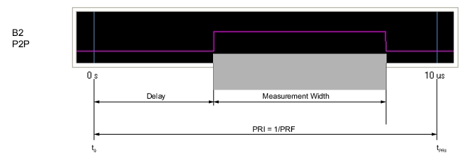
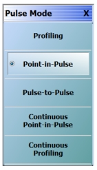 | Pulse Profiling (PROF) A measurement mode where there is an incoming pulse and it is desired to acquire S-parameters at sub-intervals within that pulse. These values are mapped versus position (time) within the pulse. This can be visualized as a profiling pulse (the sub-interval segment/measurement width) that steps through the DUT output pulse in time increments and makes a measurement at each step. This measurement is often used to check the evolution of DUT behavior over the duration of the pulse due to thermal, trapping, or other effects. Point-in-Pulse (PIP) A measurement mode where an S-parameter is only to be acquired at one time point within a pulse (or more precisely, within a small time window/measurement width). This is usually somewhere in the middle of the pulse and is selected when transient effects associated with pulse edges are not a concern, but the DUT must operate in pulsed mode (for example, to minimize device heating). It is desired to see how the behavior at the point within the pulse changes over frequency or power ranges. Pulse-to-Pulse (P2P) A measurement mode similar to pulse profiling except the time interval is between multiple pulses rather than within a pulse. Longer time-scale transient effects (such as thermal or memory related effects) are of interest. This is usually a triggered measurement since the DUT often needs to be in a long-time-scale-equilibrium before the excitation starts. Continuous Point-in-Pulse (CPIP) A measurement mode similar to Point-in-Pulse which is adequate for many swept pulse measurements. However, there are cases, particularly related to DUT transient response, where more detailed control of the VNA sweep operation relative to the pulses and the measurements is required. This is the purpose of the Continuous Point-in-Pulse mode (CPIP) where the entire sweep of frequency or power is done during one acquisition. Continuous Profiling As in CPIP, Continuous Profiling (CProf) measurement also uses a single acquisition for an entire frequency or power sweep but is a generalization in data analysis relative to CPIP. In CProf, one is not restricted to a measurement window associated with each sweep point but one can have up to 25000 measurement windows dispersed over the entire sweep time or located in some subset of that range. The number of displayed points is equal to the number of profiling points. |
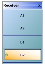 | A1 Receiver Selects the A1 receiver. A2 Receiver Selects the A2 receiver. B1 Receiver Selects the B1 receiver. B2 Receiver Selects the B2 receiver. |
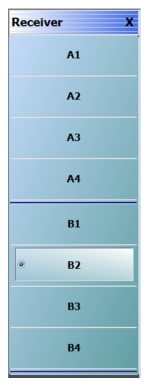 | A1 Receiver Selects the A1 receiver. A2 Receiver Selects the A2 receiver. A3 Receiver Selects the A3 receiver. A4 Receiver Selects the A4 receiver. B1 Receiver Selects the B1 receiver. B2 Receiver Selects the B2 receiver. B3 Receiver Selects the B3 receiver. B4 Receiver Selects the B4 receiver. |
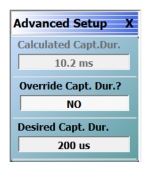 | When Advanced Setup is selected this menu is displayed allowing the user to override the calculated capture duration. Calculated Capt. Dur. Not active. Simply displays current capture duration. Override Capt. Dur? Select toggles override on and off Desired Capt. Dur. The desired capture duration maximum is dependent on the PULSEVIEW menu Resolution field entry, which can have a maximum of 14 seconds. |
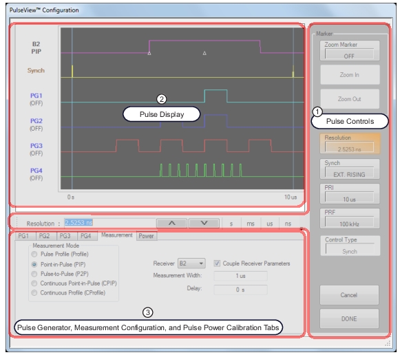 |
1. Items in the Pulse Control area are explained in Pulse Controls. 2. Items in the Pulse Display area are detailed in Pulse Display. 3. Items in the Pulse Generator, Measurement Configuration, and Pulse Power Calibration tabs are detailed in Pulse Generator Configuration, Pulse Measurement Setup, and Pulse Power Calibration Setup. |
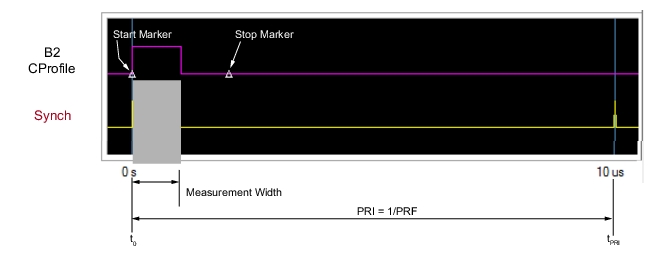
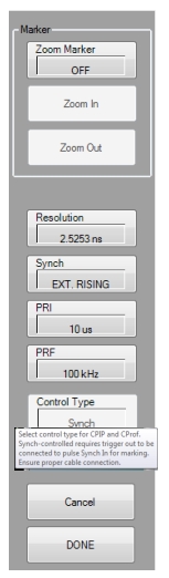 | Marker The pulse Marker feature allows up to two markers to be set on the pulse display. The marker window can then zoomed in and back out. The feature is described further in Zoom Marker Resolution Opens a field to change the pulse acquisition rate. This allows the user to speed up the measurements by changing the acquisition rate. This is useful when measurements are made at lower rep rates which may not require a high resolution. As resolution changes, the maximum values of most other PulseView settings changes (maximum acquisition length increases proportionately with resolution; default is 2.5253 ns resolution and 0.5 s maximum acquisition length). Synch Toggles the pulse Synch source: • INTERNAL synchronizes the primary clock to the leading edge of an internally provided synch pulse. • CONTINUOUS provides continuous, unsynchronized full-speed data acquisition. • EXT. RISING/EXT FALLING synchronizes the primary clock to the leading edge of an externally provided synch pulse. The synch event can be triggered to either the rising or falling edge of the synch pulse (EXT. RISING or EXT. FALLING). When the Synch type selected is EXT. RISING or EXT. FALLING, an “Ext. Synch Marking” check box is made available on the PulseView Configuration | Measurement tab. This feature allows the use of the external Pulse Synch In signal to mark the data stream in lieu of using the internally generated T0 pulsed signal. When enabled, the internal pulse generators are disabled 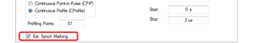 PRI Pulse Repetition Interval – Sets the primary clock synch pulse period in units of time and is inversely proportional to the pulse repetition frequency (PRI = 1 / PRF). When a PRI value is entered, the PRF is computed automatically. PRI can also be set in the PULSEVIEW SETUP Menu. PRF Pulse Repetition Frequency – Sets the primary clock synch pulse repetition rate in units of hertz and is inversely proportional to the pulse repetition interval (PRF = 1 / PRI). When a PRF value is entered, the PRI is computed automatically. PRF can also be set in the PULSEVIEW SETUP Menu. Control Type Enabled only in CPIP or CProf modes. Choices are Sync and Time. Synch control requires that Trigger Out be connected to Pulse Synch In. This is noted with a tool tip that appears when a pointer is over the button, as well as on the PULSEVIEW SETUP menu. |
Cancel Cancels all settings and closes the PULSEVIEW CONFIGURATION dialog box. Done Applies all settings and closes the PULSEVIEW CONFIGURATION dialog box. Done must be clicked to apply any setting changes made. |
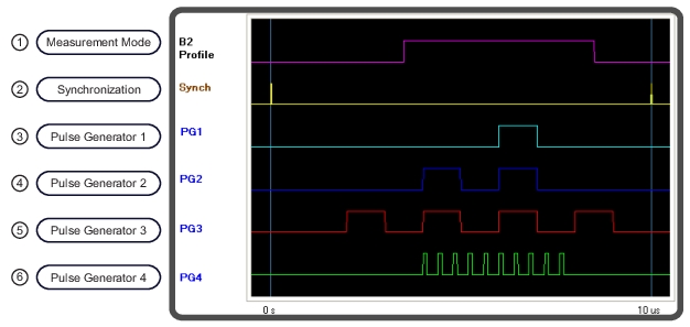 | |
1. Pulse Measurement: Width = 5 µs Start = 3.5 µs Stop = 8.5 µs 2. Pulse Synchronization Signal: Set to Internal 3. Pulse Generator 1 (PG1): Singlet Mode 6 µs Delay, 1 µs Width 4. Pulse Generator 2 (PG2): Doublet Mode 4 µs Delay 1, 1 µs Width 1 6 µs Delay 2, 1 µs Width 2 | 5. Pulse Generator 3 (PG3): Quadruplet Mode 2 µs Delay, 1 µs Width 4 µs Delay, 1 µs Width 6 µs Delay, 1 µs Width 8 µs Delay, 1 µs Width 6. Pulse Generator 4 (PG4): Burst Mode # of Bursts: 10 Period: 400 ns Delay: 4 µs Width: 50 ns |
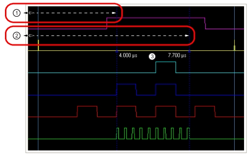 |
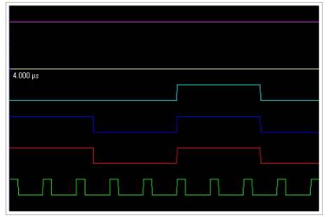
1. With the Zoom Marker toggled ON, click and drag the left edge of the display to reveal a marker. 2. Click and drag the left edge of the display to reveal a second marker. 3. Marker values change dynamically when the marker is dragged along the time axis. |
 |
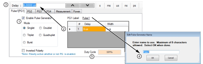 |
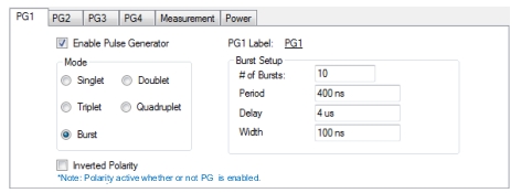
1. Select the pulse Mode and Enable the Pulse Generator. 2. Select the Delay and Width field to edit. 3. Enter the value in the field toolbar and terminate with the desired units. 4. Click the PG1 Label field and enter the desired pulse generator name (optional). 5. Duty Cycle (display only, appears with Singlet pulse mode). |
 |
Note | Delay + Width ≤ PRI |
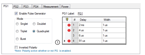 |
1. Invalid settings are indicated with a warning symbol as shown above. |
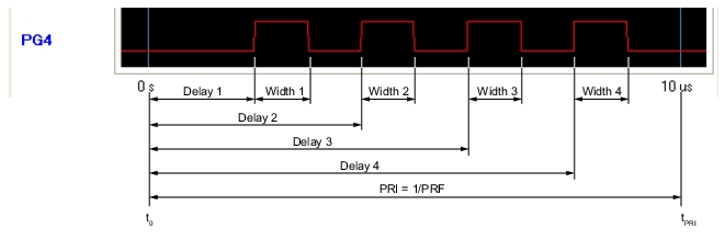 |
Note | Delay 2 > Delay 1 + Width 1 Delay 3 > Delay 2 + Width 2 Delay 4 > Delay 3 + Width 3 Delay 4 + Width 4 ≤ PRI |
 |
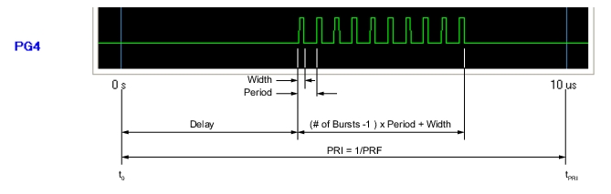 |
Note | Delay + (# of Bursts – 1) x Period + Width ≤ PRI Width ≤ Period |
Note | All receivers are set to the same mode, but the pulse acquisition parameters can be set differently between each of the receivers. |
Note | In profile mode, overlapping measurements are permitted when the measurement width is set larger than the duration between measurement points, determined by: (Stop – Start) / # of Points |
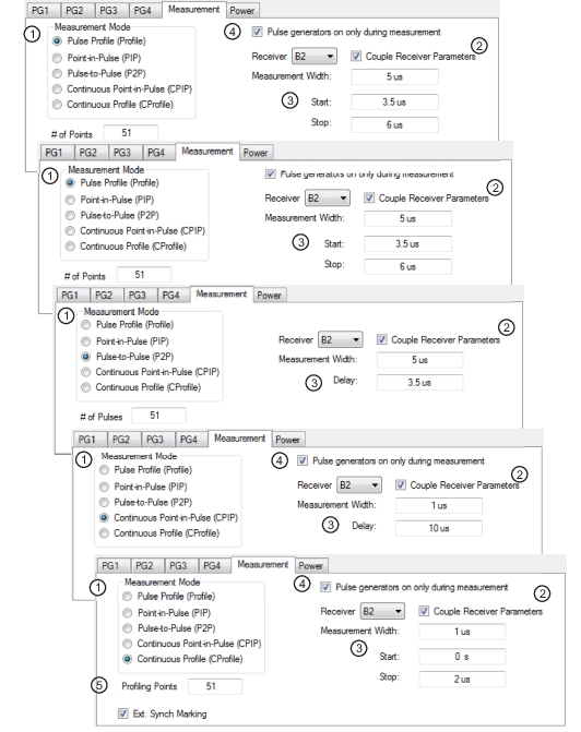 |
1. Set the measurement mode (the measurement mode is a per-channel setting that applies to all receivers). 2. Select the receiver and check if the measurement parameters are to be applied equally to all receivers. 3. Set the measurement parameters on a per-receiver or coupled basis. 4. When the Measurement tab is selected the Pulse generators on only during measurement toggle selection is only visible when measurement mode is Pulse Profile or Continuous Profile. Selecting this feature allows pulse generators to start up only when a measurement is taken. 5. In Continuous Profiling mode there is a concept of profiling points which is the number of displayed analysis points. This can be greater or less than the # of sweep points. |
 |
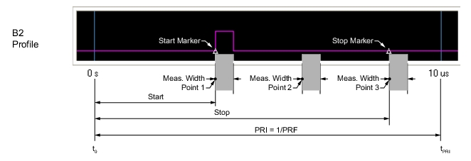 |
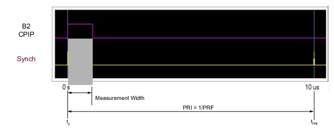
Note | Stop – Start ≤ PRI # of points ≤ instrument number of points (25k or 100k) The measurement width can overlap other measurement widths. |
 |
 |
Note | Delay + Measurement Width ≤ PRI |
 |
 |
Note | Delay + Measurement Width ≤ PRI |
 |
 |
Note | Delay + Measurement Width ≤ PRI |
 |
 |
Note | Delay + Measurement Width ≤ PRI |
 |
 |