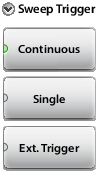
Sets the sweep trigger to internal and continuous, and sets the Run/Hold setting to Run. A new sweep is triggered automatically at the end of each sweep. This is the default sweep trigger setting.
Single
Sets the sweep trigger to internal and single, and sets the Run/Hold setting to Hold. Each sweep is activated by the Run/Hold submenu key.
Ext. Trigger
Sets the sweep trigger to an external source. Each sweep is activated by a TTL signal at the External Trigger In connector. Refer to Test Panel Connector Overview.
IFBW
The following choices are available for the intermediate frequency bandwidth setting:
100 kHz
the maximum sweep speed
50 kHz
20 kHz
10 kHz
5 kHz
2 kHz
1 kHz
default
500 Hz
200 Hz
100 Hz
50 Hz
20 Hz
10 Hz
the maximum dynamic range
RF Immunity
The instrument defaults to RF Immunity Low. When set to High, RF Immunity protects the instrument from stray signals generated by nearby or co‑located transmitters that can affect frequency and distance domain DTF measurements. The algorithm that is used to improve instrument ability to reject unwanted signals may slow down the sweep speed if interferers are detected. If the instrument is used in an environment where immunity is not an issue, then the RF Immunity key can be set to Low to optimize sweep speed. Use this feature with caution, because the introduction of an interfering signal might be mistaken for a problem with the antenna or cable run. If Immunity is set to Low during a normal measurement, then the instrument will be more susceptible to interfering signals. Interfering signals can make the measurement look better or worse than it really is.
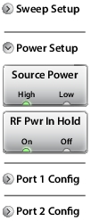
Sets the RF Output power to be left On or to be turned Off when Run/Hold is toggled to Hold. Refer to RF Pwr In Hold for details.
RF Pwr In Hold
This setting determines if the RF output power at the RF Out/Reflect In port stays On or is turned Off when the instrument Run/Hold setting is toggled to Hold. To turn off RF power at the port when the instrument is placed in Hold mode and is not sweeping, set RF Pwr In Hold to Off. Power at the port is resumed when the Run/Hold setting is toggled back to Run. This is useful when you may not want a signal radiating out of the port at all times.
Sweep Menu 3
Port 1 Config and Port 2 Config
Port 2 configuration is identical except for the port number.
Key Sequence: Sweep (3) > Port 1 Config
Sweep Menu – Port 1 Config or Port 2 Config
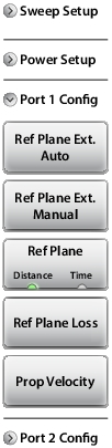
Port 1 Config or Port 2 Config
Ref Plane Ext. Auto
Press this submenu key to automatically determine the best distance or time to mathematically extend the reference plane (Plane of Calibration) in order to remove an appropriate amount of linear phase rotation from the measurement data. Refer to Reference Plane Extension Auto.
Ref Plane Ext. Manual
Press this submenu key to manually enter a distance or time to which the Reference Plane (Plane of Calibration) is extended. Refer to Reference Plane Extension Manual.
Ref Plane Distance Time
Press this submenu key to toggle the units setting between Distance and Time for the Reference Plane Extension. This setting affects both the Auto and Manual units setting of the Reference Plane Extension.
Ref Plane Loss
Press this submenu key to set the reference plane loss in dB. The entered loss value for each port is displayed in the Instrument Settings Summary above the graph area.
Prop Velocity
This value is used by the Reference Plane Extension functions (distance units). Press this submenu key to enter the propagation velocity of electrical signals in the length of cable that is being removed by the Reference Plane Extension calculations. Values are expressed as a decimal ratio compared to the speed of light in a vacuum.
Examples:
1 = speed of light, and 0.5 = 1/2 the speed of light.
Reference Plane Extension Auto
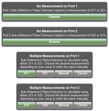
This submenu key is used to automatically determine the best distance or time to mathematically extend the reference plane (Plane of Calibration) in order to remove an appropriate amount of linear phase rotation from the measurement data. The resultant display will unwrap phase (refer to Phase versus Unwrapped Phase Graph Types) to allow a better view of the phase properties of the Device Under Test. This function can be applied to a reflection measurement (S11 for port 1 or S22 for port 2) or to a transmission measurement (S21 for port 1 or S12 for port 2), depending on the user setup. To determine the appropriate phase rotation, and depending on your display settings, you may be presented with a message box (see Figure: Message Boxes for Reference Plane Extension) asking you to specify to which S‑parameter the reference plane extension should be applied. The calculated distance value or time value for each port is displayed in the Instrument Settings Summary above the graph area.
Message Boxes for Reference Plane Extension
Reference Plane Extension Manual
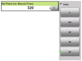
This submenu key is used to manually enter a distance or time to which the Reference Plane (Plane of Calibration) is extended. This action calculates and removes an appropriate amount of linear phase rotation (from the measurement data) based on the time or distance entered by using this submenu key. The entered distance or time value for each port is displayed in the Instrument Settings Summary above the graph area. When you enter a time or distance value, a Units menu is provided (as shown in Figure: Manual Reference Plane Extension Entry with Time Units).
Manual Reference Plane Extension Entry with Time Units