Screen images in this User Guide are illustrations of typical instrument features. Some images may include instruments other than the Site Master S820E. Traces and other display features may differ from the screen displays of your instrument.
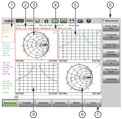
VNA Mode Display Overview
1.
Instrument Settings Summary – unique to each trace
2.
Instrument Settings Summary – applies to all traces
3.
Trace 1 (TR1)
4.
Magnifying Glass, to maximize size of trace
5.
Trace 2 (TR2)
6.
Submenu Button (Key) Labels
7.
Main Menu Button (Key) Labels
8.
Trace 4 (TR4)
9.
Trace 3 (TR3)
Chapter Overview
The S820E Site Master is a Vector Network Analyzer that can measure the magnitude and phase characteristics of 1‑port or 2‑port networks, including cables, antennas, filters, isolators, and attenuators.
VNA mode provides advantages over Cable‑Antenna Analyzer Mode via more advanced measurements, more flexibility, and more calibration choices. The main advantages are scattering parameter (S‑parameter) choices, graph type choices, and domain choices. In VNA mode, these three measurement choices can be mixed and matched to provide users with more freedom and flexibility. For simplicity in Cable‑Antenna Analyzer mode, the choices are more fixed and limited.
Advanced graph types allow you to look at the same device measurements in many different ways. The ability to display four traces provides you with the flexibility of comparing various measurements to obtain the results you need more efficiently.
Advanced graph types such as Group Delay, Real, Imaginary, inverted Smith Chart, Real Impedance, and Imaginary Impedance are available in the S820E in addition to the standard graph types, Log Mag, SWR, Phase, and Smith Chart. The S820E gives you the ability to display four traces overlaid, or they can be displayed in individual graphs.
In Cable‑Antenna Analyzer Mode, the S820E is a two‑port, 1‑path instrument. In VNA Mode, the S820E is a full‑reversing VNA that is capable of measuring all S‑parameters (S11, S21, S22, and S12) of a 2‑port device with a single connection. Being able to measure both forward and reverse S‑parameters allows you to use more advanced calibration methods and to make more accurate measurements of a 2‑port device.