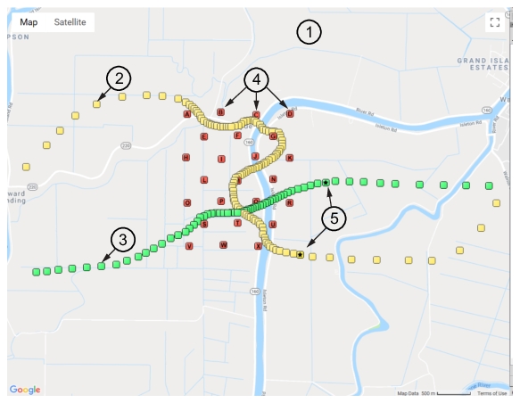
The Simulator map display provides a moving interference signal over a geographical area. Remote spectrum monitors are positioned in the area to capture signal interference activity as it moves through the monitored zone as shown in Figure: Map Activity.
Map Activity
1. Map Display
2. Source 1 Path
3. Source 2 Path
4. Target Receiver Probes
5. Source Position
Map Display
The map display is a user defined map that is applied to the GUI when Load Map or Existing Maps is clicked.
Source 1 Path
The yellow breadcrumb display simulates the path the interferer 1 signal.
Source 2 Path
The green breadcrumb display simulates the path the interferer 2 signal.
Target Receiver Probes
24 Remote Spectrum Monitor probes can be positioned on the map as indicated. The letter of each probe position corresponds to the Port probe listed in the first column. With the mouse pointer over one of the simulator GPS coordinates, scroll the mouse wheel back and forth. This will adjust the GPS coordinates and move the on-map icon. Click the Control button while scrolling and see that the icon moves in the parallel direction.
Source Position
Indicates the current position of the tracked signal. The Step Interval setting determines the speed of each step through the path. Click on a track point on the map to change and set the current interferer location. The tracking point list corresponds to the changed tracking point that is set.Simulator Probes and Emitter Tracking.
Features of the map control include:
• Zoom and pan control with the mouse.
• Zoom control with the slider in the lower right-hand corner of the map.
• Right-click the map to view the context menu.
• Move the mouse around and view the latitude and longitude coordinates are displayed at the bottom edge of the map.
The simulator probes and emitters displayed on the GUI map provide a visual tracking of the signal source emitters and probes. Red markers are simulator probe positions. Yellow markers are RF emitters. A Interferer Configuration in the middle of a marker represents the current active emitter as described above.
Emitter Position and Control
Activate an emitter on the map by either clicking it’s marker on the map, or by clicking the marker coordinates that are listed on the right side of the screen. Each time a different emitter is selected, the markers are redrawn to indicate which one is active.
Add or Remove an Emitter
Add an emitter to the list by double-clicking on the map. Remove an emitter from the list by clicking the emitter in the list and click the ‘Delete’ key. You cannot reposition an emitter, except to delete and add a new one in the desired location.
Sorting the Displayed Emitters
You can change the order of the emitters in the list. Click one and press the keypad Ctrl-Up or Ctrl-Down. This moves the selected item up or down in the list. From the menu bar, press Tracks, then Sort Tracks to resort the entire list so that each emitter follows the one closest to it.
When sorting, the first emitter does not change positions. The closest to the first geographically is moved to the second position, the next closest to the second item is then moved to the third position and so forth. This makes it possible to add and delete emitters along a desired path and then order them at any time.
Saving a List of Emitters
Once you have created a list of emitters, you will want to save the list to a file. This is done with the ‘Save’ button in the toolbar. The saved list can be reloaded using the ‘Load’ button.
When saving, the entire configuration is saved, including the list of simulated probes with their sweep configuration, GPS coordinates, the interferer location and power, and other program settings. All parameter settings in the panel on the left side of the program window is saved and reloaded.