To select channel power measurement go to main menu and press MEASURE > MEASUREMENT >Channel Power. The channel power measurements are set up using the SETUP Menu (Channel Power). Channel power measurement is one of most common measurements for a radio transmitter. This test measures the output power, or channel power, of a transmitter over the frequency range. Out‑of‑specification power measurements indicate system faults, which can be in the power amplifiers or in filter circuits. Channel Power measurements can be used to validate transmitter performance, comply with government regulations, or to keep overall system interference at a minimum.
Channel Power Measurement
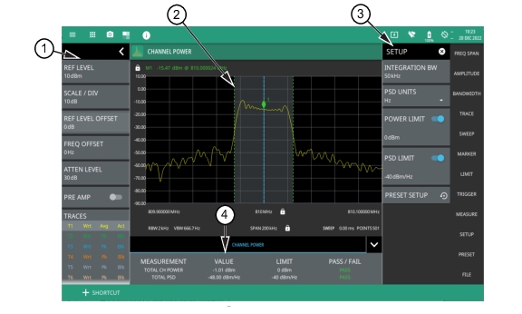
1. The status panel provides quick access to common spectrum analyzer settings. See STATUS PANEL (Channel Power).
2. Dashed vertical lines and a shaded region define the main channel integration bandwidth.
2. Channel power measurement results are shown in a table at the bottom of the display.
Frequency and span settings for many signal standards can be set as follows:
1. Select MEASURE on the main menu.
2. Select Channel Power from the MEASUREMENT button.
3. Select SETUP and then do the following:
• Set the channel INTEGRATION BW (bandwidth).
• Select PSD UNITS (Hz or MHz).
• Toggle and set the POWER LIMIT and PSD limit testing if you wish to see pass/fail test results.
Channel Power is a constant measurement; after it is turned on, it remains on until a different measurement is selected or the sweep is paused. Channel Power is calculated at the end of each sweep.
STATUS PANEL (Channel Power)
Below is the status panel with the corresponding minimized status panel icons for channel power measurement.
Status Panel with Minimized Status Panel Icons (Channel Power)
REF LEVEL
Sets the reference level of the top graticule line in the selected units. If the reference level offset is not zero, OFFSET REF LEVEL is displayed at this location. Refer to Setting Amplitude Parameters.
SECOND REF LEVEL
The reference level is the top graticule line to the right on the measurement display. Its functionality is exactly same as reference level, but it is only available when trace math is enabled.
SCALE/DIV
Sets the graticule scale/division for log-based units. This setting does not apply to linear units.
SECOND SCALE/DIV
It applies to second reference level and is available only when trace math is enabled.
REF LEVEL OFFSET
Sets the reference level offset in dB units. This setting can compensate for the presence of external input attenuation or gain.
Displays the current status of up to six traces or cursors in a quick-view summary. When the measurement view is set to RF Spectrum, trace information is displayed in this area. When the measurement view is set to Spectrogram, cursor information is displayed in this area. Cursors are available in the Spectrum measurement with the Spectrogram view selected.
The summary information includes the trace or cursor number, type, mode, and detector type. The active trace will show a highlighted background with the mode and detector type restated under the table. In Spectrogram, a reference trace (T0) will show you the settings of the trace used to fill the spectrogram. The reference trace settings are applied to all traces and cursors while in Spectrogram view. Selecting a trace or cursor in the summary panel activates the pressed trace or cursor and opens the TRACE menu, allowing you to select and set up an individual trace or cursor as desired. Refer to Setting Trace Parameters.
SWEEP
Toggles the current sweep setting between continuously or sweep once. Refer to Setting Sweep Parameters.
FREQ REFERENCE
Indicates the current frequency reference source of Internal High Accuracy (used after GPS has lost sync, but while the internal clock still has good GPS reference), Internal Standard Accuracy, External, or GNSS (GPS) Hi Accuracy (requires GPS). The instrument automatically selects the frequency reference in the following order of priority: external, GPS, then the internal time base.
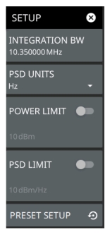
SETUP Menu (Channel Power)
The channel power SETUP menu is available in MEASURE > MEASUREMENT > Channel Power > SETUP. Once the channel power measurement is selected, the SETUP menu can be quickly accessed by tapping on the summary display area below the spectrum window.
SETUP Menu (Channel Power)
INTEGRATION BW
Sets the range of integration used in calculating the power in the channel. The integration bandwidth (IBW) is displayed as the shaded region between the bandwidth start and stop thresholds (dashed green lines).
PSD UNITS
Sets the unit bandwidth for power spectral density. The available units are Hz and MHz.
POWER LIMIT
The power limit is the threshold value used to determine whether the actual measured channel power will pass or not. If the measured channel power exceeds the set power limit, the channel power test fails; otherwise, the test passes. Pass/fail test results are shown in the measurement results table.
PSD LIMIT
If the power spectral density limit is on, the PSD Limit is the threshold value used to determine whether the actual measured PSD will pass or not. If the measured PSD exceeds the PSD Limit, the PSD test fails; otherwise the test passes.
PRESET SETUP
Sets all channel power setup parameters to default. Turns off limits.