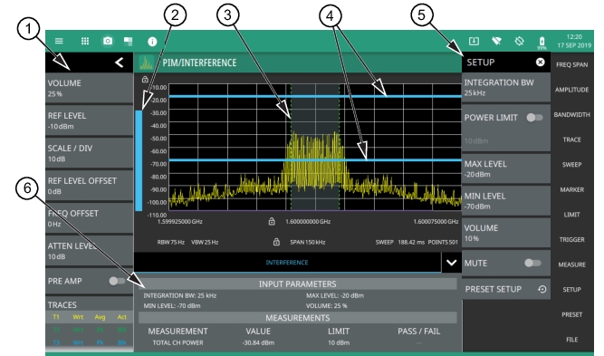
To select PIM/Interference measurement go to main menu and press MEASURE > MEASUREMENT >PIM/Interference. The PIM/interference measurement is set up using the SETUP Menu (PIM/Interference). The interference finder measurement is used in conjunction with a directional antenna to locate the direction of an interfering signal. This test measures the integrated power of a received signal over a specified frequency range. During the measurement, the instrument emits an audio tone that coincides with the power of the received signal. As the antenna is pointed toward the signal source, the signal level increases further into the set MAX and MIN level, and the audio increases in pitch. An example of a frequency modulated interfering signal is shown in the figure below.
6. Interference setup parameters and measurement results are shown in a table at the bottom of the display.
Frequency and level settings for many interfering signals can be set as follows:
1. Select MEASURE on the main menu.
2. Select Interference from the MEASUREMENT button.
3. Select SETUP and then do the following:
• Set the signal INTEGRATION BW (bandwidth).
• Toggle and set the POWER LIMIT if you wish to see pass/fail test results.
• Set the MAX LEVEL and MIN LEVEL for the audio pitch response of the measurement. Note that these settings can also be dragged into position using the indicator bars in the display panel.
• Set the desired volume level. Note that the audio level can also be set from the left side status menu.
Interference Finder (Option 24) is a constant measurement; after it is turned on, it remains on until a different measurement is selected or the sweep is paused. Signal power and a corresponding audio pitch is calculated at the end of each sweep.
Note
Some directional antennas have a narrower null than their forward beam width; therefore, it may be more precise to find the null at the back of the directional antenna to determine the direction of the interfering signal. In this case, you would look for the lowest signal level and the corresponding audio would have the lowest pitch.
STATUS PANEL (PIM/Interference)
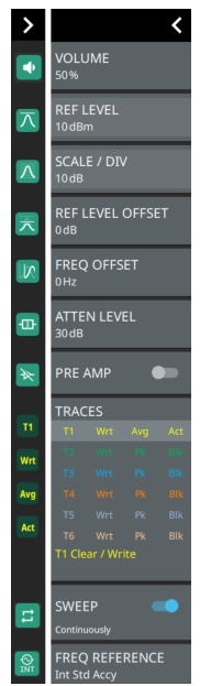
Below is the status panel with the corresponding minimized status panel icons for interference measurement.
Status Panel with Minimized Status Panel Icons (Interference Finder)
VOLUME
Sets the volume level for the audio response of the measurement. Note that the system volume can affect the range of this setting.
REF LEVEL
Sets the reference level of the top graticule line in the selected units. If the reference level offset is not zero, OFFSET REF LEVEL is displayed at this location.
Displays the current status of up to six traces or cursors in a quick-view summary. When the measurement view is set to RF Spectrum, trace information is displayed in this area. When the measurement view is set to Spectrogram, cursor information is displayed in this area. Cursors are available in the Spectrum measurement with the Spectrogram view selected.
The summary information includes the trace or cursor number, type, mode, and detector type. The active trace will show a highlighted background with the mode and detector type restated under the table. In Spectrogram, a reference trace (T0) will show you the settings of the trace used to fill the spectrogram. The reference trace settings are applied to all traces and cursors while in Spectrogram view. Selecting a trace or cursor in the summary panel activates the pressed trace or cursor and opens the TRACE menu, allowing you to select and set up an individual trace or cursor as desired. Refer to Setting Trace Parameters.
SWEEP
Toggles the current sweep setting between continuously or sweep once. Refer to Setting Sweep Parameters.
FREQ REFERENCE
Indicates the current frequency reference source of Internal High Accuracy (used after GPS has lost sync, but while the internal clock still has good GPS reference), Internal Standard Accuracy, External, or GNSS (GPS) Hi Accy (requires GPS). The instrument automatically selects the frequency reference in the following order of priority: external, GPS, then the internal time base.
SETUP Menu (PIM/Interference)
The interference finder SETUP menu is available in MEASURE > MEASUREMENT > PIM/Interference > SETUP. Once the interference measurement is selected, the SETUP menu can be quickly accessed by tapping on the summary display area below the spectrum window.
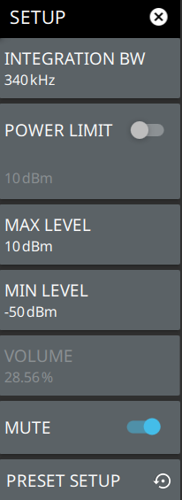
SETUP Menu (PIM/Interference)
INTEGRATION BW
Sets the range of integration used in calculating the received power. The integration bandwidth is displayed as the shaded region between the bandwidth start and stop thresholds (dashed green lines).
POWER LIMIT
The power limit is the threshold value used to determine whether the actual measured channel power will pass or not. If the measured channel power exceeds the set power limit, the channel power test fails; otherwise, the test passes. Pass/fail test results are shown in the measurement results table.
MAX LEVEL
Sets the upper level for the audio response of the measurement. This setting is useful for adjusting the resolution of the tone changes. Power levels above the MAX LEVEL will continue to emit sound an increasingly higher pitch.
MIN LEVEL
Sets the lower level for the audio response of the measurement. The MIN LEVEL also functions as a squelch. Power below this level will not emit a sound.
VOLUME
Sets the volume level for the audio response of the measurement. Note that the system volume can affect the range of this setting. Refer to PIM/Interference (Option 24).
MUTE ALL
Mutes the volume of the instrument.
PRESET SETUP
Presets all values on the SETUP menu to default values.