 |
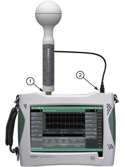
Note | EMF measurements require that an Anritsu EMF isotropic antenna is connected to the analyzer and that the frequency range and span is set within the operating range of the antenna. |
|
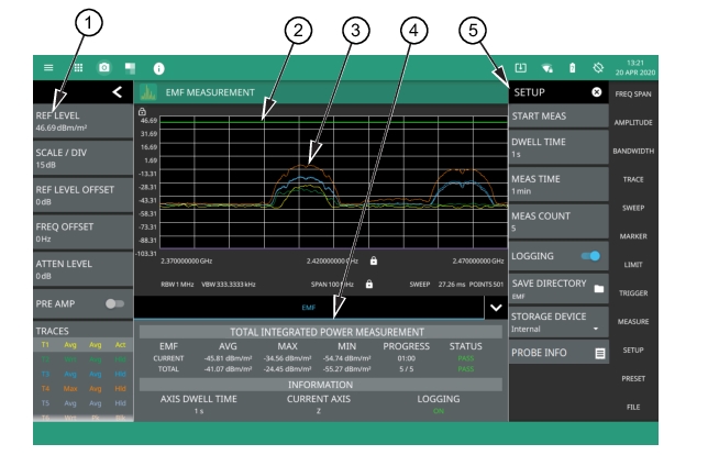 |
1. The status panel provides quick access to common spectrum analyzer settings. See STATUS PANEL (EMF Measurement). 2. EMF measurement pass/fail status uses a limit line for the test criteria. You can use either a custom limit line or toggle the International Commission on Non-Ionizing Radiation Protection limit. Either limit supports the same features as in the spectrum analyzer mode. See LIMIT Menu. 3. The trace display area shows traces for the following measurements in units/m2: • Trace 1: Current axis sweep data • Trace 2: Current isotropic result • Trace 3: Average isotropic result • Trace 4: Maximum isotropic result • Trace 5: Total average isotropic result Note that trace detectors and trace averaging are disabled for the EMF measurement. 4. Tabular measurement data shows the current and total EMF measurement results, the current test progress, and the pass/fail status. The information area shows the axis dwell time, the current axis being measured, and the data logging state. 5. Use the SETUP menu to configure the EMF measurement settings. See SETUP Menu (EMF Measurement). |
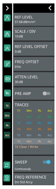 | REF LEVEL Sets the reference level of the top graticule line in the selected units. If the reference level offset is not zero, OFFSET REF LEVEL is displayed at this location. Refer to Setting Amplitude Parameters. SCALE/DIV Sets the graticule scale/division for log-based units. This setting does not apply to linear units. REF LEVEL OFFSET Sets the reference level offset in dB units. This setting can compensate for the presence of external input attenuation or gain. FREQ OFFSET Accounts for frequency conversions outside of the analyzer. Refer to Setting Frequency Parameters. ATTEN LEVEL When auto attenuation is off, sets input attenuation. PRE AMP Toggles the low-noise front-end preamplifier on or off. Refer to Setting Amplitude Parameters. TRACES/CURSORS Displays the current status of up to six traces or cursors in a quick-view summary. When the measurement view is set to RF Spectrum, trace information is displayed in this area. When the measurement view is set to Spectrogram, cursor information is displayed in this area. Cursors are available in the Spectrum measurement with the Spectrogram view selected. The summary information includes the trace or cursor number, type, mode, and detector type. The active trace will show a highlighted background with the mode and detector type restated under the table. In Spectrogram, a reference trace (T0) will show you the settings of the trace used to fill the spectrogram. The reference trace settings are applied to all traces and cursors while in Spectrogram view. Selecting a trace or cursor in the summary panel activates the pressed trace or cursor and opens the TRACE menu, allowing you to select and set up an individual trace or cursor as desired. Refer to Setting Trace Parameters. SWEEP Toggles the current sweep setting between continuously or sweep once. Refer to Setting Sweep Parameters. FREQ REFERENCE Indicates the current frequency reference source of Internal High Accuracy (used after GPS has lost sync, but while the internal clock still has good GPS reference), Internal Standard Accuracy, External, or GNSS (GPS) Hi Accy (requires GPS). The instrument automatically selects the frequency reference in the following order of priority: external, GPS, then the internal time base. | |
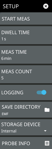 | START MEAS Initiates an EMF measurement. Once the measurement is started, all UI interface is locked until the measurement is complete. A pop-up control appears that allows you to immediately stop the measurement. Note that a valid antenna must be connected and a supported frequency range must be set before a measurement can be started. Note that the START MEAS button also appears on the MEASURE menu and provides the same functionality. DWELL TIME Specifies the time to sweep on each of the three isotropic antenna axis (X, Y, and Z). The sweeps are then averaged and saved for further computation. Note that if the sweep time is longer than the dwell time setting, the sweep time will determine the time spent on each axis (a complete sweep must be completed before moving to the next axis). MEAS TIME Sets the duration of each EMF measurement from one minute up to 30 minutes. The default is 6 minutes. The measurement time includes all of the sweeps for each axis, which repeats until the total measurement time is completed. For example, if the axis dwell time is set to 1 second (and the sweep time is 1 second or less) and the measurement time is set to 1 minute, you will get one complete isotropic result after 3 seconds, and approximately 20 isotropic results at the end of the one-minute measurement. The CURRENT row in the summary table at the bottom of the screen displays a running average of the isotropic results, and the max and min of the computed total integrated power of the isotropic results every 3 s. The displayed values are computed from all measurements completed thus far within the measurement time. At the end of the measurement time, the CURRENT row is cleared and the TOTAL row is updated with the max, min, and running average of all isotropic results (20 in this example). MEAS COUNT Sets the number of EMF measurements (set in MEAS TIME) to complete from 1 up to 10,000. The EMF test is fully executed when the specified number of measurements have completed. LOGGING Logging is toggled on by default. This must be selected prior to starting the EMF measurement for the results to be logged. Each log file can hold 21 measurements for a maximum of 10,000 measurements total. All files for a measurement run will be stored in the same folder with the year, month, day, measurement time and number. SAVE DIRECTORY Sets the directory of where the log folders are created. STORAGE DEVICE Sets the storage location of either Internal memory or an externally connected storage device. PROBE INFO Displays the details of the connected isotropic antenna, for e.g. frequency range, hardware revision etc. |