To select carrier-to-interference (C/I) measurement go to main menu and press MEASURE > MEASUREMENT >C/I measurement. The C/I measurement is set up using the SETUP Menu (C/I).Carrier-to-interference (C/I) measurement is the ratio of the total RF power in the defined integration bandwidth, including transmitter power, noise, interference and distortion, to the power in the channel when the transmitter is turned off.
This measurement is commonly required in satellite downlink testing and land mobile radio (LMR) system testing. In order to complete this measurement the carrier power should be turned off in a controlled way.
The C/I ratio is calculated as:
C/I = Carrier Power – Interference Power
The C/I can be measured by following the instructions below:
1. Select C/I under MEASUREMENT drop-down of MEASURE menu.
2. Select the SETUP menu.
3. Set the center frequency to the wanted transmitter’s center frequency value.
4. Set the span that enables a view of the full carrier channel with some additional margin.
5. Set the integration bandwidth for the measurement. This will typically be the channel bandwidth for the signal standard under test.
6. Toggle on AUTO TIME to perform a single sweep at the maximum rate for measuring power when the transmitter is on and off. Toggle off AUTO TIME when the noise, interference and distortion has a significant time dependency. By setting a slow sweep time, the noise and interference from time variable signals can be integrated in the measurement.
7. Connect the RF input to the signal under test with the wanted transmitter ON.
8. Start the measurement by selecting START MEAS.
9. When prompted, select CONTINUE to measure the carrier power.
10. To measure noise, interference and distortion over the same integration bandwidth turn off the transmitter without disconnecting the RF connection.
11. Select CONTINUE to measure the noise, interference and distortion in the channel.
12. Select FINISH to complete the measurement, or CANCEL to stop the measurement.
13. Verify the measurement values such as Carrier power (transmitter ON), Interference power (Noise, Interference and distortion (transmitter OFF), and the C/I ratio displayed in the C/I table.
Note
The C/I measurement is performed in a single sweep mode. To enable continuous sweep, toggle on SWEEP Continuously button.
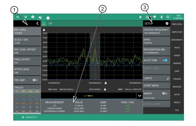
Carrier-to-Interference measurement
1. Status panel provides quick access to all the spectrum analyzer menu settings. See STATUS PANEL (C/I).
2. The C/I table shows the carrier-to-interference ratio (dB), carrier power and interference power measured in dBm.The Pass/Fail status is populated only if the limits are toggled on in LIMITS menu.
3. The SETUP menu is where the C/I settings are configured. See SETUP Menu (C/I).
The power in the interference part of the measurement can result from different sources:
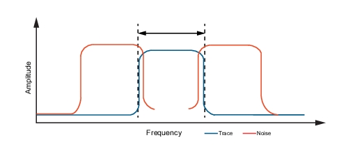
• Adjacent Channel Power overlapping into the wanted channel
Adjacent Interference
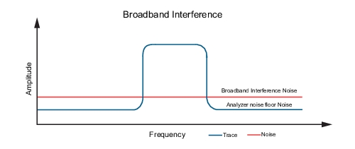
• Broadband Noise
Broadband Noise
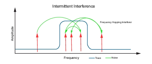
• Power from Intermittent or frequency hopping noise
Intermittent Interference
STATUS PANEL (C/I)
Below is the status panel with the corresponding minimized status panel icons for C/I measurement.
Status Panel with Minimized Status Panel Icons (C/I)
REF LEVEL
Sets the reference level of the top graticule line in the selected units. If the reference level offset is not zero, OFFSET REF LEVEL is displayed at this location.
Displays the current status of up to six traces or cursors in a quick-view summary. When the measurement view is set to RF Spectrum, trace information is displayed in this area. When the measurement view is set to Spectrogram, cursor information is displayed in this area. Cursors are available in the Spectrum measurement with the Spectrogram view selected.
The summary information includes the trace or cursor number, type, mode, and detector type. The active trace will show a highlighted background with the mode and detector type restated under the table. In Spectrogram, a reference trace (T0) will show you the settings of the trace used to fill the spectrogram. The reference trace settings are applied to all traces and cursors while in Spectrogram view. Selecting a trace or cursor in the summary panel activates the pressed trace or cursor and opens the TRACE menu, allowing you to select and set up an individual trace or cursor as desired. Refer to Setting Trace Parameters.
SWEEP
Toggles the current sweep setting between continuously or sweep once. Refer to Setting Sweep Parameters.
FREQ REFERENCE
Indicates the current frequency reference source of Internal High Accuracy (used after GPS has lost sync, but while the internal clock still has good GPS reference), Internal Standard Accuracy, External, or GNSS (GPS) Hi Accy (requires GPS). The instrument automatically selects the frequency reference in the following order of priority: external, GPS, then the internal time base.
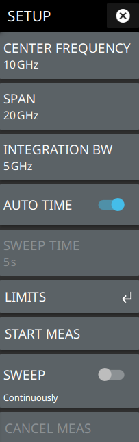
SETUP Menu (C/I)
The C/I SETUP menu is available in MEASURE > MEASUREMENT > C/I > SETUP.
SETUP Menu (C/I Measurement)
CENTER FREQUENCY
Sets the center frequency of the sweep range.
SPAN
Sets the sweep frequency range. Selecting the plus (+) or minus (–) control increments the span value in a 1:2:5 sequence. The span can also be changed by pinching the trace in or out when gestures are not toggled off.
INTEGRATION BW
Sets the range of integration used in calculating the power in the channel. The integration bandwidth (IBW) is displayed as the shaded region between the bandwidth start and stop thresholds (dashed green lines).
AUTO TIME
Toggle this button off to manually set the sweep time using the numeric entry keypad.
SWEEP TIME
Allows to set full manual sweep time range to measure the intermittent or frequency hopping noise.
LIMITS
Opens LIMITS Menu.Toggle on the C/I, carrier power and interference power limit buttons to verify the PASS/FAIL status of the measured values with respect to the set limits.
START MEAS
Starts the wizard or sequence of message windows to measure carrier power followed by noise power.
SWEEP CONTINUOUSLY
Toggle on to enable continuous sweep. Toggle off to freeze the signal or stop the instrument from sweeping.
CANCEL MEAS
Cancels the measurement of carrier power and/or interference power.
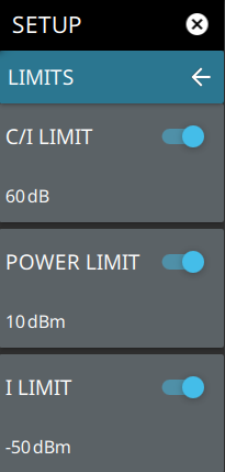
LIMITS Menu
SETUP Menu (C/I Measurement)
C/I LIMIT
Sets the carrier-to-interference ratio limit in dB. Enter the desired C/I ratio (dB) limit value using the numeric keypad.
POWER LIMIT
Sets the desired value of the carrier power limit. Enter the desired carrier power (dBm) limit value using the numeric keypad.
I LIMIT
Sets the desired value of the interference power limit. Enter the desired interference power (dBm) limit value using the numeric keypad