Occupied bandwidth measurements are set up using the SETUP Menu (Occupied BW). Occupied Bandwidth (OBW) is a common measurement performed on radio transmitters. This measurement calculates the bandwidth containing the total integrated power occupied in a given signal bandwidth. There are two different methods of calculation depending on the technique used to modulate the carrier.
• % Integrated Power Method: The occupied frequency bandwidth is calculated as the bandwidth containing the specified percentage of the transmitted power.
• > dBc Method: The occupied frequency bandwidth is defined as the bandwidth between the upper and lower frequency points at which the signal level is a desired number of dB below the peak carrier level.
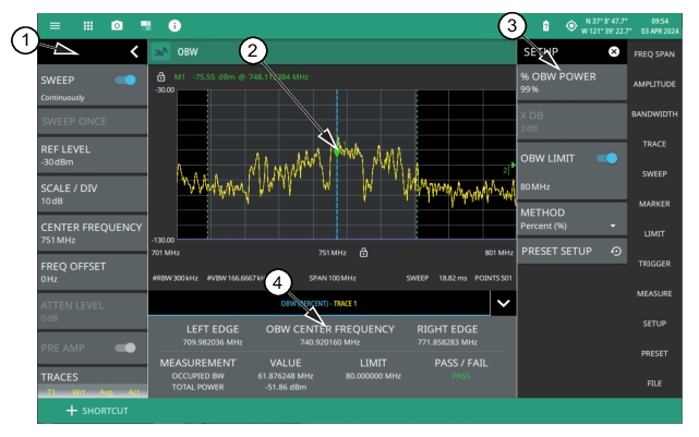
WCDMA Occupied Bandwidth (OBW) Measurement
1. The status panel provides quick access to common spectrum analyzer settings. See STATUS PANEL (Occupied BW).
2. Dashed vertical lines and a shaded region define the main channel.
3. All occupied bandwidth measurement parameters are set via the SETUP menu. See SETUP Menu (Occupied BW).
4. Occupied bandwidth measurement results are shown in a table at the bottom of the display.
Frequency and span settings for many signal standards can be set as follows:
1. Select MEASURE on the main menu.
2. Select OBW from the MEASUREMENT button.
3. Select SETUP and then do the following:
• Set the % OBW power or set X DB (dBc) power value
• Select the METHOD (Percent (%) or dBc (X DB)
• Toggle OBW limit testing if you wish to see pass/fail test results
Occupied bandwidth is a constant measurement; after it is turned on, it remains on until a different measurement is selected or the sweep is paused. OBW is calculated at the end of each sweep.
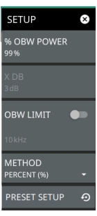
SETUP Menu (Occupied BW)
The occupied bandwidth SETUP menu is available in MEASURE > MEASUREMENT > OBW > SETUP. Once the OBW measurement is selected, the SETUP menu can be quickly accessed by tapping on the summary display area below the spectrum display.
SETUP Menu (Occupied BW)
% OBW POWER
Sets the percentage of the total power that is measured within the occupied bandwidth for the current measurement. The resulting occupied bandwidth and total power values are displayed in the measurements results table.
X dB
Sets the x dB value used for the "x dB bandwidth" measurement. The occupied bandwidth is the frequency range between two points on the signal that are x dB down from the highest signal point within the OBW span.
OBW LIMIT
Enables limit checking at the specified frequency. The limit test results show as a green PASS or a red FAIL in the measurement table.
METHOD
Select the measurement method to be PERCENT (%) or X (dB).
PRESET SETUP
Sets all OBW setup parameters to default. Turns off limits.
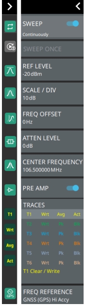
STATUS PANEL (Occupied BW)
Below is the status panel with the corresponding minimized status panel icons for occupied bandwidth measurement.
Status Panel and Minimized Status Panel Icons (WCDMA OBW Measurement)
SWEEP: Toggles the current sweep setting between continuously or sweep once.
SWEEP ONCE
When sweep is set to single sweep, SWEEP ONCE updates the measurement display. Data continues to be captured in the background.
REF LEVEL
Sets the reference level of the top graticule line in the selected units. If the reference level offset is not zero, OFFSET REF LEVEL is displayed at this location. Refer to Setting Amplitude.
SCALE/DIV
Sets the graticule scale/division for log-based units. This setting does not apply to linear units.
FREQ OFFSET
Accounts for frequency conversions outside of the analyzer.
ATTEN LEVEL
When auto attenuation is off, sets input attenuation.
CENTER FREQUENCY
Sets the center frequency of the sweep range. The current span setting will remain constant or will be adjusted to accommodate the start and stop frequency range of the instrument. The center frequency can also be dragged on the display when gestures are not toggled off.
PRE AMP
Turns the low-noise front-end preamplifier on or off. To ensure accurate measurement results, the largest signal into the instrument input when the preamplifier is turned on should be less than –40 dBm. The preamplifier cannot be turned on if auto attenuation is on and the reference level is above –40 dBm.
TRACES
Displays the current status of up to six traces in a quick-view summary. The summary information includes the trace number, type, mode, and detector type. The active trace will show a highlighted background with the mode and detector type restated under the table. Pressing a trace in the summary panel activates the pressed trace and opens the TRACE menu, which allows you to select and set up an individual trace as desired. Refer to Setting Trace Parameters.
FREQ REFERENCE
Indicates the current frequency reference source of Internal, External, or GNSS (GPS) Hi Accuracy (requires GPS). The instrument automatically selects the frequency reference in the following order of priority: external, GNSS (GPS), then the internal time base.