 |
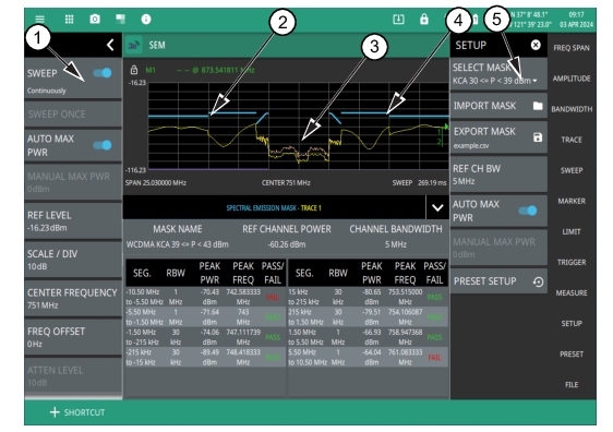
1. The status panel provides quick access to common spectrum analyzer settings. See STATUS PANEL (SEM). 2. SEM Mask 3. Spectrum Emission 4. SEM Mask 5. All SEM measurement parameters are set via the SETUP menu. See SETUP Menu (SEM). |
|
1. The status panel provides quick access to common spectrum analyzer settings. See STATUS PANEL (SEM). 2. SEM Mask 3. Spectrum Emission 4. SEM Mask 5. All SEM measurement parameters are set via the SETUP menu. See SETUP Menu (SEM). |
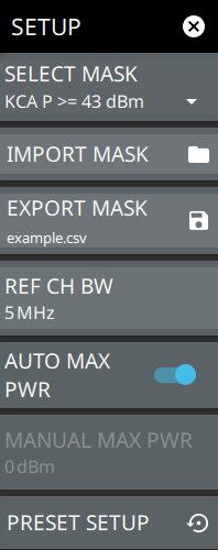 | SELECT MASK Selects the desired upper/lower or custom emission mask. Choose the desired mask from the list. IMPORT MASK Used to import a custom user mask. EXPORT MASK Exports an example user mask as a comma separated value file (see Example Custom Signal Emission Mask) or exports the currently selected custom mask. REF CH BW Sets the reference channel bandwidth for the measurement. AUTO MAX PWR Toggles automatic max power. Some segments in the mask are dependent on the main channel power. Enabling this automatically calculates the reference channel power by measuring the channel power of the center channel bandwidth. When disabled, the reference power must be entered manually below. MANUAL MAX PWR Used to manually enter the reference channel power for masks that have limits dependent on main channel power. PRESET SETUP Presets all values on the SETUP menu to default values. |
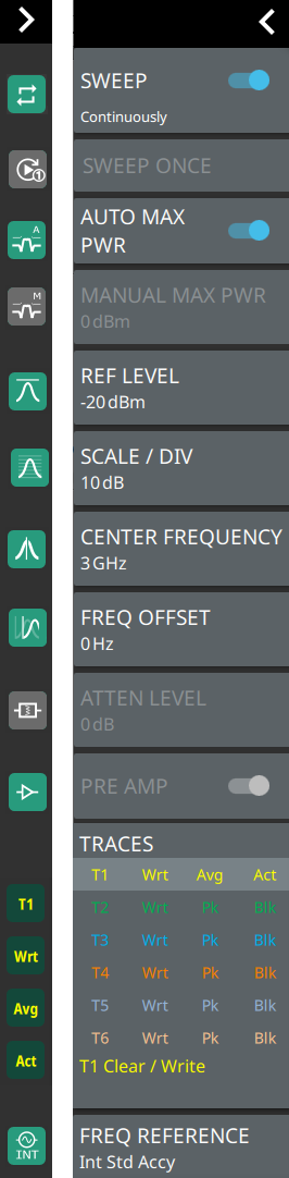 | SWEEP Toggles the current sweep setting between continuously or sweep once. Refer to Setting Sweep Parameters. SWEEP ONCE When sweep is set to single sweep, SWEEP ONCE updates the measurement display. Data continues to be captured in the background. AUTO MAX PWR Toggle auto maximum power to set the maximum power automatically. MANUAL MAX PWR Enables when Auto Max Power is toggled. REF LEVEL Sets the reference level of the top graticule line in the selected units. If the reference level offset is not zero, OFFSET REF LEVEL is displayed at this location. Refer to Setting Amplitude Parameters. SCALE/DIV Sets the graticule scale/division for log-based units. This setting does not apply to linear units. FREQ OFFSET Accounts for frequency conversions outside of the analyzer. Refer to Setting Frequency and Bandwidth Parameters. ATTEN LEVEL When auto attenuation is off, sets input attenuation. CENTER FREQUENCY Sets the center frequency of the sweep range. The current span setting will remain constant or will be adjusted to accommodate the start and stop frequency range of the instrument. The center frequency can also be dragged on the display when gestures are not toggled off. PRE AMP Toggles the low-noise front-end preamplifier on or off. Refer to Setting Amplitude Parameters. TRACES Displays the current status of up to six traces in a quick-view summary. The summary information includes the trace number, type, mode, and detector type. The active trace will show a highlighted background with the mode and detector type restated under the table. Pressing a trace in the summary panel activates the pressed trace and opens the TRACE menu, which allows you to select and set up an individual trace as desired. Refer to Setting Trace Parameters. FREQ REFERENCE Indicates the current frequency reference source of Internal High Accuracy (used after GPS has lost sync, but while the internal clock still has good GPS reference), Internal Standard Accuracy, External, or GNSS (GPS) Hi Accy (requires GPS). The instrument automatically selects the frequency reference in the following order of priority: external, GPS, then the internal time base. | |