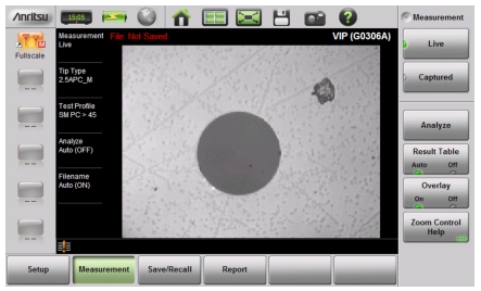
Once the Video Inspection Probe is properly connected and you have started the VIP application on the Site Master, a live view of the optical fiber endface should display on the instrument screen. See Figure: VIP Image Live View.
VIP Image Live View
Note
Instead of capturing and analyzing a live VIP image, you can recall a previously saved image and perform VIP analysis on it. Refer to Recall a VIP Image (VIP Mode Only).
VIP Image Analysis
Skip the first three steps below if the displayed VIP image is a recalled image.
1. While the display is in Live view, adjust the image focus if needed.
2. Press the Measurement main menu key to display the Measurement menu, shown in Figure: VIP Image Live View.
3. Press the Captured key to capture the VIP image.
4. Optionally, use the rotary knob and arrow keys to zoom and pan the image, respectively. The Zoom Control Help key displays the related Help message.
5. To execute the VIP image analysis, press the Analyze submenu key. Skip this step if the Auto Analyze setting is On, in which case the image is automatically analyzed when captured (refer to the Setup Menu).
After the analysis completes, the overall Pass/Fail indicator is displayed in the lower left corner of the screen.
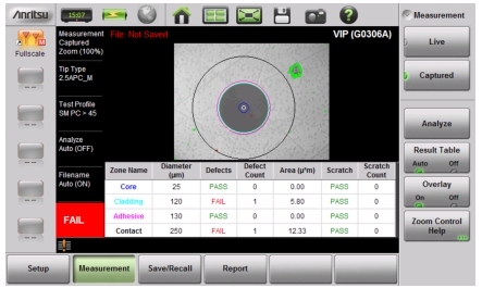
6. Press the Results Table submenu key to show or hide the detailed analysis results. See Figure: VIP Image Captured and Analyzed. For each of the analysis areas, or zones (core, cladding, adhesive, contact), the table shows the count of scratches and contaminations or defects, and their Pass/Fail evaluation results. The table will not appear if there are no analysis results to display.
VIP Image Captured and Analyzed
7. Press the Overlay submenu key to turn on and off the colored circles around the analysis areas, and the red and green highlights showing the defects and scratches found on the connector endface. Defects of an acceptable size are green (Pass). Defects that are large enough to potentially cause a problem are highlighted in red (Fail).
8. To save the VIP data to file with one press of the touchscreen, press the Save icon in the System Function Tool Bar. The current auto filename settings are applied to the saved file, provided the Auto Filename submenu key is set to On. Refer to VIP Test Settings.
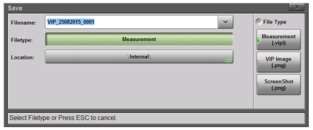
If Auto Filename is Off, or if you press the Save/Recall main menu key followed by Save, or press Save (7) on the numeric keypad, the Save dialog is displayed. See Figure: Save Dialog Box.
10. To select the type of file to save, press the Filetype button, then press the desired submenu key. See Figure: VIP File Type.
Measurement (.vipi) – Saves the VIP image and analysis results
VIP Image (.png) – Saves the VIP image only
ScreenShot (.png) – Saves a screen capture of the current display
VIP File Type
11. Optionally, press the Location button and select the destination folder as described in Save Location.
12. Press the Save button in the Save dialog.
If the overall analysis result is a Fail, follow standard practices to clean or replace the fiber optic connector.
VIP Reporting
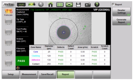
You can output the captured VIP image and analysis results to a PDF-formatted file, using the Report main menu key. The report may include current or previously saved data, or both.
VIP Report Menu
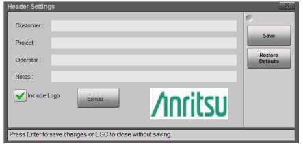
1. Press Header Settings to enter or change the report header data.
VIP Report Header Settings Dialog
2. In the Header Settings dialog box, press the text field to be edited and use the touchscreen keyboard to enter the information.
3. If you want the report to show your company logo, select the Include Logo checkbox and browse to the location of the desired logo image. This image must be in PNG format, and will be resized automatically.
4. Press Save to save the header information, which is retained until modified.
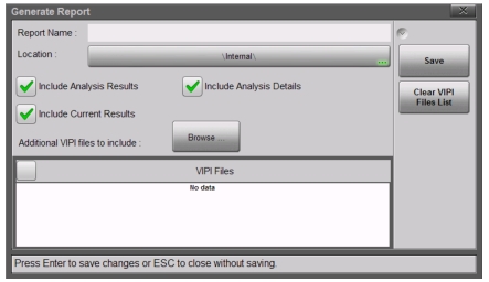
6. Enter the report name and select the destination folder as needed.
7. Optionally, press the Clear VIPI Files List button to remove saved files from the list included in the report.
8. Select or deselect the checkboxes as appropriate:
Analysis Results – Overall Pass/Fail result Analysis Details – Detailed results by analysis area Current Results – Image and analysis results of currently displayed VIP measurement Additional VIPI Files – Previously saved measurement data