The toolbar shown in Figure: Capture Toolbar provides controls for saving streaming data and interfacing with the analyzer. The PC software initiates IQ streaming on the analyzer when the Stream IQ Data toolbar button is clicked. The software reads the IQ data stream over Ethernet or the PCIe interface and stores the data on the PC.
Note
A high-speed SSD is recommended for PCIe streaming and high bandwidth settings.
The IQ streaming and storage can be set to a fixed time or stopped at any time by clicking the Stop IQ Stream button.
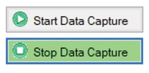
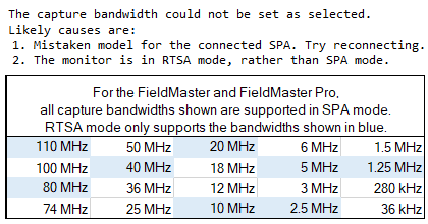
Start Data Capture initiates IQ data streaming and saves the streaming data to the output folder (see Capture Menu Settings Window). After it is pressed, the button changes to Stop Data Capture. Press and the data streaming is stopped. It is only enabled if the analyzer is connected and the correct options are installed. The button will be unavailable if a required option is missing or if a connection via the selected streaming port is not established. Captures that are performed when the Spectrum Analyzer is set to RTSA mode require the capture Bandwidth to be set as shown in the warning dialog below.
The Sync function is not active when grayed. Press to provide synchronized capture across multiple PC/Monitor pairs. See Sync Button.
Opens Windows Explorer to the output folder location.
Deletes all supported streaming files (.dgz, .dgzm, .biq, .xdat, .xml, .xhdr) in the specified output folder. (see Capture Menu Settings Window)
Factory reset restores the analyzer to the factory default settings for all measurement modes and system settings, including language and the display and audio settings. Ethernet settings and user files are not affected. The analyzer will automatically restart. Factory reset could be useful to correct an erroneous analyzer setting that might affect the IQ stream as it is the surest way to get the analyzer back into a known good state. A message is displayed and the user can choose whether to continue with this action.
After the reset, the analyzer will need reconfiguring and the IQ Acquisition software will need to be restarted if using PCIe.
Sync Button
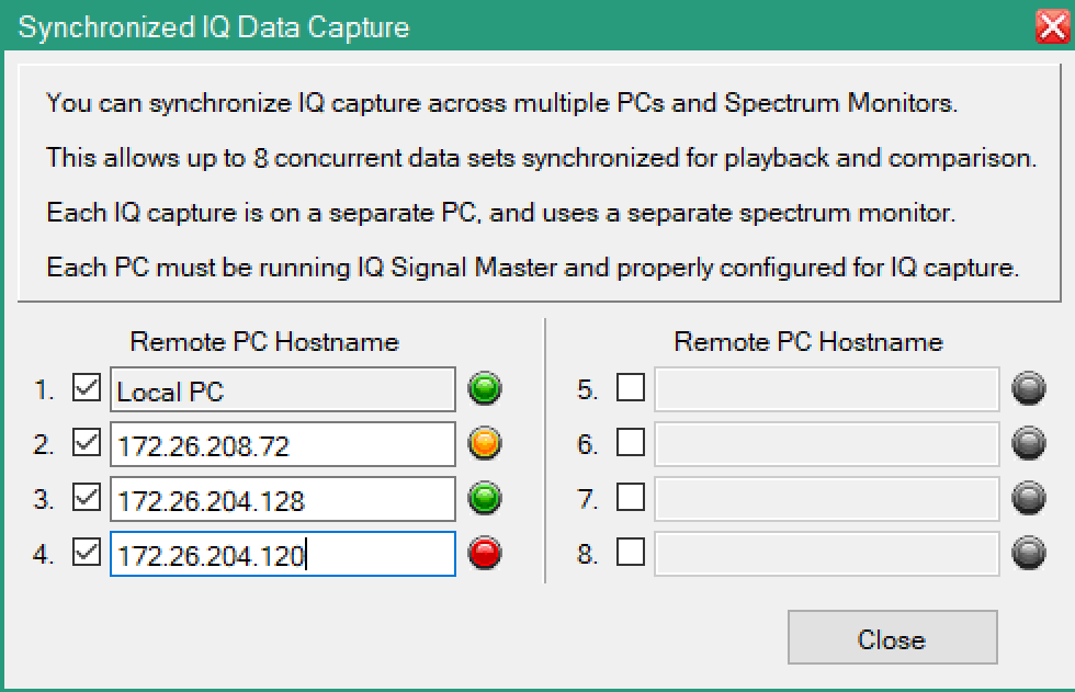
Press Sync to display the dialog shown in Figure: Synchronized IQ Data Capture Dialog to synchronize IQ capture across multiple PCs and Spectrum monitors. This provides up to eight concurrent data sets synchronized for playback and comparison. Each IQ capture is on a separate PC and uses a separate spectrum monitor. Each PC must be running IQ Signal Master and be properly configured for IQ capture.
Synchronize Across Several PCs
To obtain synchronized captures across several PCs running IQ Signal Master, see Connection Options.
Pres the Start Capture Button will start capture on remote PCs.
Synchronized IQ Data Capture Dialog
Connection Indicators
The connection indicators provide a IQ capture connectivity status of the PC running IQ Signal Master to the spectrum analyzer.
Green
The PC with the IP Hostname entry is running the IQ Signal Master and is connected to a spectrum analyzer ready for data capture.
Yellow
The PC with the IP Hostname entry is running the IQ Signal Master and is not connected to a spectrum analyzer.
Red
The PC with the IP Hostname entry is not running the IQ Signal Master.
Capture Menu Settings Window
The Capture menu settings window provides a variety of settings for the interface to the analyzer as well as some basic measurement setup parameters. The following underlined parameters (Center Frequency, Capture Bandwidth, Reference Level, and Attenuation) shown in Figure: IQ Acquisition Parameter Settings Window are interactive with the analyzer. Click on the parameter label to send the setting immediately to the analyzer.
Analyzer URL
Enter the analyzer URL or IP address. The indicator to the left is described below:
• Green LED: A connection has been established with the analyzer and the required option is installed. The "Stream IQ Data” button will be enabled.
• Gray LED: No connection to the analyzer has been attempted.
• Red LED: No analyzer is found or an analyzer is found missing option 125 or 127. Streaming is disabled.
Streaming Port
Provides Ethernet and PCIe as streaming port types. See Set Streaming Port.
Continuous Mode
IQ data will continue creating a series of output files until stopped. Each time the target file size or collection size is met, a new file will be created. The IQ stream will not be continuous across files and there will be a gap.
Stop on Errors
Enabled for PCIe only. The PCIe interface can detect if a byte is wrong. This setting is on by default. Uncheck to continue streaming data even if a transfer error is detected.
Center Frequency
Sets the analyzer’s center frequency. The setting takes affect when the Stream IQ Data is clicked.
Capture Bandwidth
Sets the analyzer’s streaming bandwidth. The list of allowed streaming bandwidths is adjusted to match the specific analyzer option. The setting takes affect when the Stream IQ Data is clicked.
Reference Level
Sets the analyzer’s reference level. The setting takes affect when the Stream IQ Data is clicked.
Attenuation
Press to send the set attenuation level to the spectrum analyzer.
Auto-Attenuation
Turn On/Off the Auto-attenuation on the spectrum analyzer.
Preamp State
Turn On/Off the preamp state on the spectrum analyzer. This may be overwritten by the analyzer firmware if the power is too high.
Capture Bit Depth
Set the analyzer’s streaming bit depth. The capture bit depth for MS27201A, MS2080A, MS2089A and MS2090A starts with I phase followed by Q phase, but for MS27100A, MS27101A, MS27102A and MS27103A it starts with Q phase followed by I phase. The capture bit depth can be structured with following options:
• 8 Bit Integer (IIIIQQQQ)
• 10 Bit Integer (IIIQQQ)
• 16 Bit Integer (IQIQ)
• 16 Bit Integer (IIQQ)
• 32 Bit Integer (IQ)
• 32 Bit Float (IQ)
Time Stamp
Include time stamps in the IQ data. This will reduce the bit depth by one bit.
Output Format
Sets the streamed data file and accompanying metadata file formats:
• Raw IQ (DGZ): This is the native format of the Anritsu SPA. For bit-depths < 32 bits, the I and Q values are ordered in a proprietary way, and programs not specifically designed to support our DGZ files will not be able to read these. Metadata is stored in an accompanying .dgzm file.
• Binary IQ (BIQ): This format undoes the I/Q pair ordering of Anritsu’s proprietary format. I/Q values are written to the file in consecutive pairs. This file format is more easily read by third party software. For 32-bit files, there is no difference. Metadata is written to an .xml file. Binary IQ files cannot be loaded for Playback and Analysis.
• Wave I/Q (wav): This output format is restricted to a 4G limit.
Output Folder
Underlined and active. Click to open the user designated output folder in Windows File Explorer. This field sets the streamed data file and accompanying metadata file location where each filename is the time stamp of the data stream. The PC hostname is now appended to the filename as shown below when:
• The capture location is on a network drive. This is to distinguish the source of a capture and to stop possible filename conflicts when doing synchronized captures to the same network location.
• The Listen for synchronization requests setting is active in the main program Settings dialog. When this is active, captures may be synchronized across several PCs.
Create Subfolder
A time stamped folder is created each time a new transfer is started. This is most useful if Continuous Mode is on as then all related files are stored in a common location.
Load After Capture
A new data files will be automatically loaded for playback and analysis after the IQ capture is complete. Since loading a large file for the first time takes considerable time, this is automatically turned OFF if the expected file size is over 256 MB. The text changes to red to visually indicate the change. You can turn this back ON after setting the capture size if you want to load the file for playback and analysis.
Output File
A display-only field of the current data transfer file name.
Run Length Control
Continuous: Streaming will continue until:
• The user presses “Stop”
• Out of space (transfer stops with about 2 GB remaining).
• An error is detected (If Stop on Errors is checked).
Size: Size is in Gigabits. Streaming will continue until:
• The current file reaches the set file size and Continuous Mode is Off.
• Continuous Mode is set to Off during capture. The stream will end when the current file size limit is reached. The user presses “Stop”.
• Out of space (transfer stops with about 2 GB remaining).
• An error is detected (If Stop on Errors is checked).
Time: Streaming will continue until:
• The current stream time reaches the set time and Continuous Mode is Off.
• Continuous Mode is set to Off during capture. The stream will end when current file elapsed time reaches the set time. The user presses “Stop”.
• Out of space (transfer stops with about 2 GB remaining).
• An error is detected (If Stop on Errors is checked).
Capture Status
The Capture Status field provides the following informational progress of the IQ capture.