To select AM/FM Audio measurement go to main menu and press MEASURE > MEASUREMENT > AM/FM Audio. To select RF Spectrum view go to MEASURE > VIEW> RF Spectrum. The AM/FM audio measurement is set up using the SETUP Menu (AM/FM Audio RF Spectrum). This section describes the AM/FM audio demodulation capability (available with Option 24) and key characteristics of analog amplitude modulation (AM) and frequency modulation (FM). The AM/FM audio measurement provides the following features:
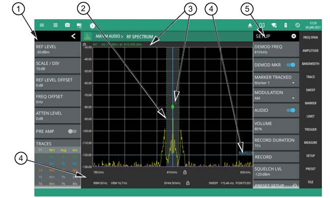
• Ability to listen to audio and sweep trace data simultaneously with built-in speaker or headphone. See Figure: AM/FM Audio (RF Spectrum).
• Selectable demodulation frequency with ability to tie frequency to markers.
• Record audio to WAV file
• Selectable modulation modes such as:
• AM
• Upper sideband (US Band)
• Lower sideband (LS Band)
• Narrowband FM
• 6.25 kHz
• 12.5 kHz
• 25 kHz
• FM Wideband
Refer to the previous sections in this chapter for details and menu overviews of general spectrum analysis measurements including setting up frequency and bandwidth parameters, sweep settings, trigger types, attenuator options, and preamp settings.
Note
The AM/FM Audio measurement (Option 24 or Option 509) remains unresponsive when PCIe is selected as Data Out Format in IQ streaming mode. Refer to IQ STREAMING Menu (Option 125/127).
AM/FM Audio – RF Spectrum View
The RF spectrum view displays the carrier signal power of the demodulated AM/FM audio signal in frequency domain.Toggle DEMOD MARKER button to identify the peak value of the carrier power. You can also record the audio signal by setting the duration time. Make sure to toggle on the Audio button to listen to the signal by adjusting the volume accordingly.
AM/FM Audio (RF Spectrum)
1. The status panel provides quick access to common spectrum analyzer settings. See STATUS PANEL (AM/FM Audio).
2. The trace display area can show multiple traces, each with a unique color. Each trace can be set to Clear/Write, Average, Min or Max Hold, Rolling Average or Rolling Min, or Max Hold. Each trace can have Peak, RMS/Average, or Negative detectors. Traces can be set to Active, Hold/View, or Blank. Refer to Setting Trace Parameters. The shaded vertical section marked with green dashed line illustrate the demodulation channel bandwidth.
3. The demodulation marker is the same as a regular marker and can be applied to any trace using the Marker Menu. Refer to Setting Up Markers.
The default view of AM/FM Audio measurement is RF spectrum view. The AM/FM audio demodulation SETUP menu is available in MEASURE > MEASUREMENT > AM/FM Audio > SETUP.
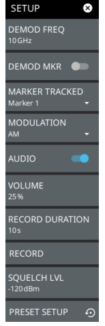
SETUP Menu (AM/FM Audio – RF Spectrum)
DEMOD FREQ
Sets the audio demodulation frequency.
DEMOD MKR
Toggles the tracked marker on and sets the demod frequency to track the marker frequency. Use the MARKER Menu to adjust the marker parameters.
MARKER TRACKED
Selects which marker to track. When DEMOD MKR is enabled, the demodulated frequency tracks the indicated marker.
MODULATION
Selects the modulation type to demodulate the RF signal. Available modulation types are AM, US Band (upper sideband), LS Band (lower sideband), FM Narrowband (6.25 12.5 and 25 kHz), and FM Wideband.
AUDIO
Toggles the demodulated audio output (sound) on or off. The demodulation frequency must be within the current sweep for audio demodulation. Slide ON the toggle button to listen to the audio signal. Note that AM/FM audio demodulation cannot be used in conjunction with IQ Streaming or when the IQ streaming output port is set to Data Out.
VOLUME
Sets the percentage of audio output volume.
RECORD DURATION
Sets the audio recording time. The maximum recording time is approximately 27 hours, depending on available storage.
RECORD
Starts audio recording. Recorded audio files (.wav) are saved to the Waves folder. Audio will be recorded for the recording duration or will stop when AUDIO is toggled off.
SQUELCH LVL
Sets the RF threshold level for audio playback. This is typically used with weak or intermittent signals to mute the static sound when the signal is below the squelch threshold.
PRESET SETUP
Presets all the AM/FM audio setup parameters.
Note
For simultaneous audio demodulation and trace sweep, the set span must not be greater than the maximum capture bandwidth based on the installed bandwidth option (No option: 20 MHz; Option 103: 55 MHz; Option 104: 110 MHz) and the tuning range must not cross more than one internal local oscillator tuning points. These conditions will be indicated by a transient status message at the top of the display.